
Varactor and varactor system

a varactor and varactor technology, applied in the field of varactors and varactor systems, can solve problems such as disadvantages in sensitivity to acceleration, and achieve the effects of increasing the electrostatic force effect, and reducing the sensitivity of adsorption

Active Publication Date: 2016-03-29
ROHDE & SCHWARZ GMBH & CO KG
View PDF4 Cites 0 Cited by
  • Summary
  • Abstract
  • Description
  • Claims
  • Application Information

AI Technical Summary

Benefits of technology

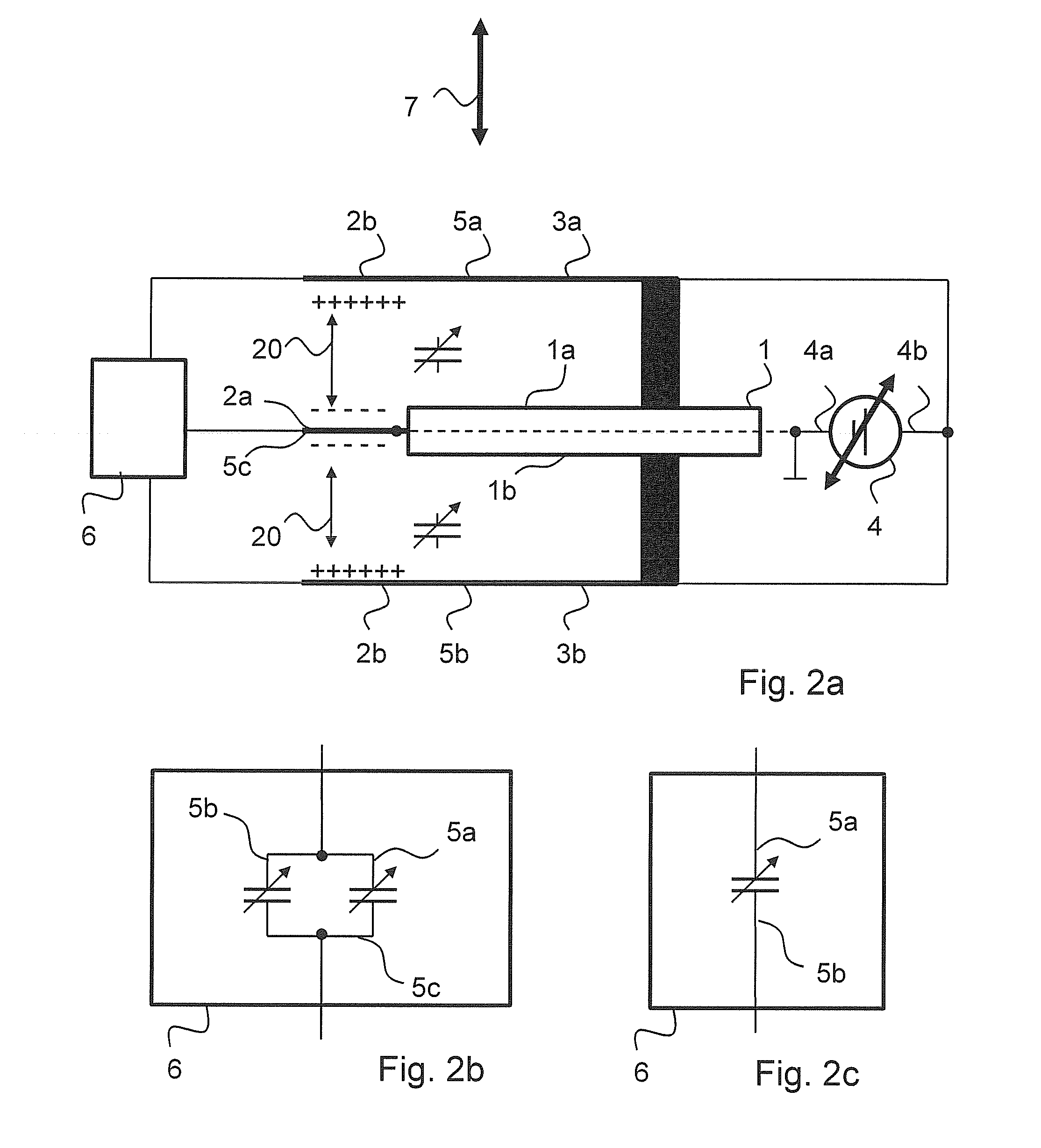
The invention relates to a type of component called a varactor, which can control the flow of electrical current. When an acceleration force is applied to the varactor, both membranes move in the same direction, which increases the distance between the first membrane and the first actuator surface, but reduces the distance between the second membrane and the first actuator surface. This change in capacitance value between the first membrane and the first actuator surface is in fact increased, while the capacitance value between the second membrane and the first actuator surface is reduced. This decoupling from interference voltages ensures that the varactor is less sensitive to interference. The invention also proposes a design with reduced tuning gradient, increased tuning range, and resistance to acceleration, even with a few varactors.

Problems solved by technology

This sensitivity to acceleration is disadvantageous if the varactor is supposed to provide an adjustable but constant capacitance value, for example, for applications in information technology and high-frequency technology.

Method used


Image

  • Varactor and varactor system
  • Varactor and varactor system
  • Varactor and varactor system

Examples


Embodiment Construction

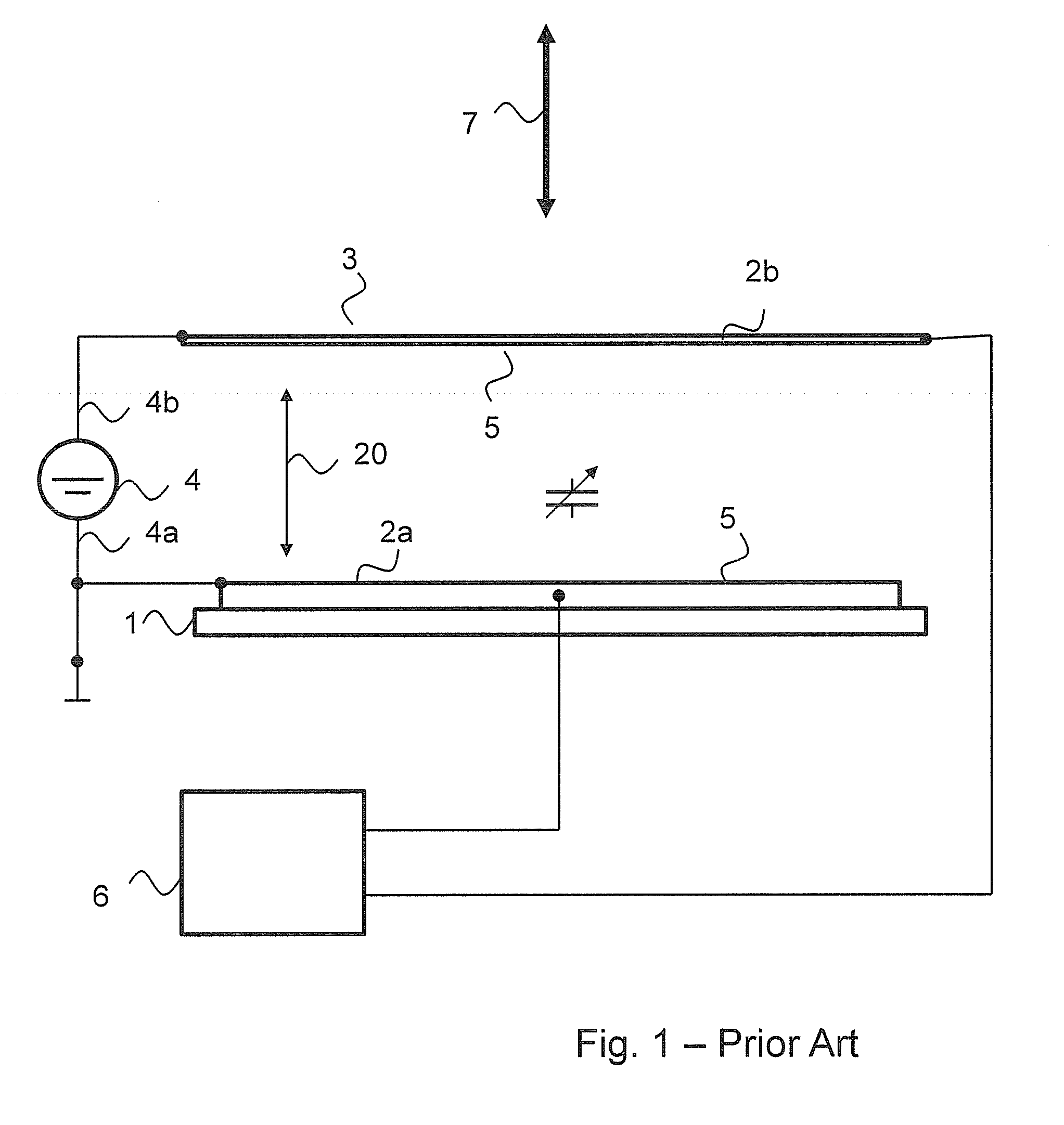
[0057]FIG. 1 shows a varactor according to the prior art. This varactor is manufactured using MEMS technology. The varactor provides a substrate 1 on which at least one first actuator surface 2a is embodied. A movable membrane 3 is arranged above the substrate 1. The membrane 3 is embodied to be electrically conductive.

[0058]The functioning of the varactor according to FIG. 1 will now be described. The actuator surface 2a on the substrate 1 is connected in an electrically conducting manner to a first terminal 4a of a direct-voltage source 4. The membrane 3 is connected in an electrically conducting manner to a second terminal 4b of the direct-voltage source 4. Accordingly, the movable membrane 3 is a second actuator surface 2b. By applying the direct voltage by means of the direct-voltage source 4, an electrostatic force 20 is formed between the first actuator surface 2a and the second actuator surface 2b. Because of the spring constant of the material of the movable membrane 3, the...


PUM


Abstract

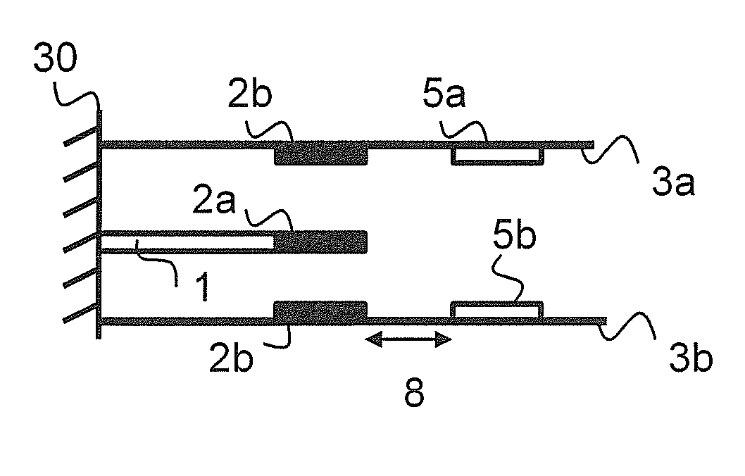
The invention relates to a varactor with an actuator, wherein the first actuator surface (2a) of the actuator is embodied on a substrate (1), and a second actuator surface (2b) is embodied on a first movable membrane (3a). In this context, the first movable membrane (3a) is arranged above an upper side (1a) of the substrate (1). A second movable membrane (2b) is arranged below a lower side (1b) of the substrate (1) facing away from the upper side (1a). The invention further relates to a varactor system made from two such varactors.

Description

FIELD OF THE INVENTION[0001]In high-frequency technology, varactors are used as tunable capacitors to vary the properties of circuits. For this purpose, a variable direct voltage is applied to the varactor, wherein the varactor behaves like a capacitor with capacitance dependent upon the direct voltage.[0002]Hitherto, semiconductor diodes based on silicon or gallium-arsenide have been used as varactors. Such varactors are also referred to as varicaps or capacitance diodes.BACKGROUND OF THE INVENTION[0003]An alternative approach to the manufacture of varactors is to realise them using micro-system technology, also designated as Micro-Electro-Mechanical Systems, abbreviated as MEMS. A MEMS part is a miniaturised part of which the components provide dimensions in the micrometer range. The individual components work together as a system.[0004]MEMS-based varactors provide a metallic membrane which is mounted in a movable manner above an actuator electrode. If a direct voltage is applied ...

Claims


Application Information

Patent Timeline
Patent Type & Authority Patents(United States)
IPC IPC(8): H01G5/16B81B7/00B81B3/00
CPCH01G5/16B81B3/0078B81B7/00B81B2201/0221
Inventor KAHMEN, GERHARD
Owner ROHDE & SCHWARZ GMBH & CO KG
Learn More