Optical system for imaging distortions in moving reflective sheets

a reflective sheet and optical system technology, applied in the field of optical devices, can solve the problems of causing distortion, difficult to achieve critical temperature uniformity over many square meters, and affecting the effect of optical distortion

Inactive Publication Date: 2008-03-18
LITESENTRY LLC
View PDF27 Cites 41 Cited by
  • Summary
  • Abstract
  • Description
  • Claims
  • Application Information

AI Technical Summary

Benefits of technology

[0023]The system described below allows the full surface area of each glass sheet to be monitored for distortion, regardless of the size of individual glass sheets, the number of glass sheets placed side by side on the conveyor, or the location of glass sheets on the conveyor. This represents a substantial improvement over the prior-art automatic measuring systems, because tempering oven conveyors are typically loaded with glass sheets that differ in size and position on the conveyor.
[0024]An optical apparatus for measuring lens power of optical distortion of reflective sheets is also disclosed. The disclosed apparatus comprises a conveyor having a transport direction (y) and a width (x) transverse to the transport direction. This conveyor transports reflective sheets, such as glass sheets, along the transport direction as they emerge from a heat treatment process. A light source is mounted on a first side of the conveyor, and this light source is constructed to direct a pattern of white circles on a black background over the entire width of the glass conveyor. One or more cameras are mounted on either side of the conveyor and are oriented to detect the reflected (or transmitted) images and measure the magnification of each. According to one aspect of the invention, the incident image spans the entire width of the conveyor, then measures lens power in both X and Y dimensions over the entire area of the sheets. The apparatus described allows the full surface area of each glass sheet to be measured for lens power, regardless of the size of individual glass sheets, the number of glass sheets placed side by side on the conveyor, or the location of glass sheets on the conveyor. The apparatus described measures and quantifies distortion over the entire surface of large glass sheets. The apparatus quantifies and records distortion in lens power in real-time on a production line. Real-time measurement and feedback allows the glass manufacturer to control the heat treatment processes and thereby control the distortion to acceptable levels.

Problems solved by technology

Achieving the critical temperature in a uniform manner over many square meters is difficult without softening the glass.
The glass is transported on heat-resistant ceramic rollers, and gravity causes the softened glass to distort.
Typical distortion is caused by sag in the glass between the rollers.
When a glass sheet is conveyed out of the furnace, quenched, finished and ultimately installed in a building, the distortions due to tempering are noticeably visible.
Beyond some tolerable level, such distortions are considered unacceptable, and the finished windows are rejected.
The distortions caused by sag between the rollers or by an out-of-round roller tend to be cyclic in nature and to produce a corrugation effect in the glass sheet.
While the glass industry quality standards specify an allowable peak-to-valley roller wave measurement, it has been difficult to accurately or easily measure roller wave distortion on the factory floor.
Physical measurements are generally limited to only a small sample, due to the time required to measure with a dial indicator gauge.
These physical measurements tend to be operator dependent with poor repeatability and are prone to error.
Such tests may be destructive, often scratching the surface of the glass as the dial indicator gauge is rolled over the surface.
Roller wave distortions cause the straight diagonal lines of the zebra board to appear wavy in reflection.
While helpful and inexpensive, a zebra board has limited use as a quality control tool.
Operators vary in their quality judgments, and consistent quality control is therefore difficult to achieve.
There is no way to consistently quantify and document the results.
Operators with the tasks of labeling, sorting and unloading glass have limited time for roller wave inspection.
When a glass sheet is fabricated and installed in a building window, an automobile, or a mirror, local distortions attributable to tempering or annealing may be noticeably visible.
Optical distortion is considered unacceptable beyond tolerable thresholds.
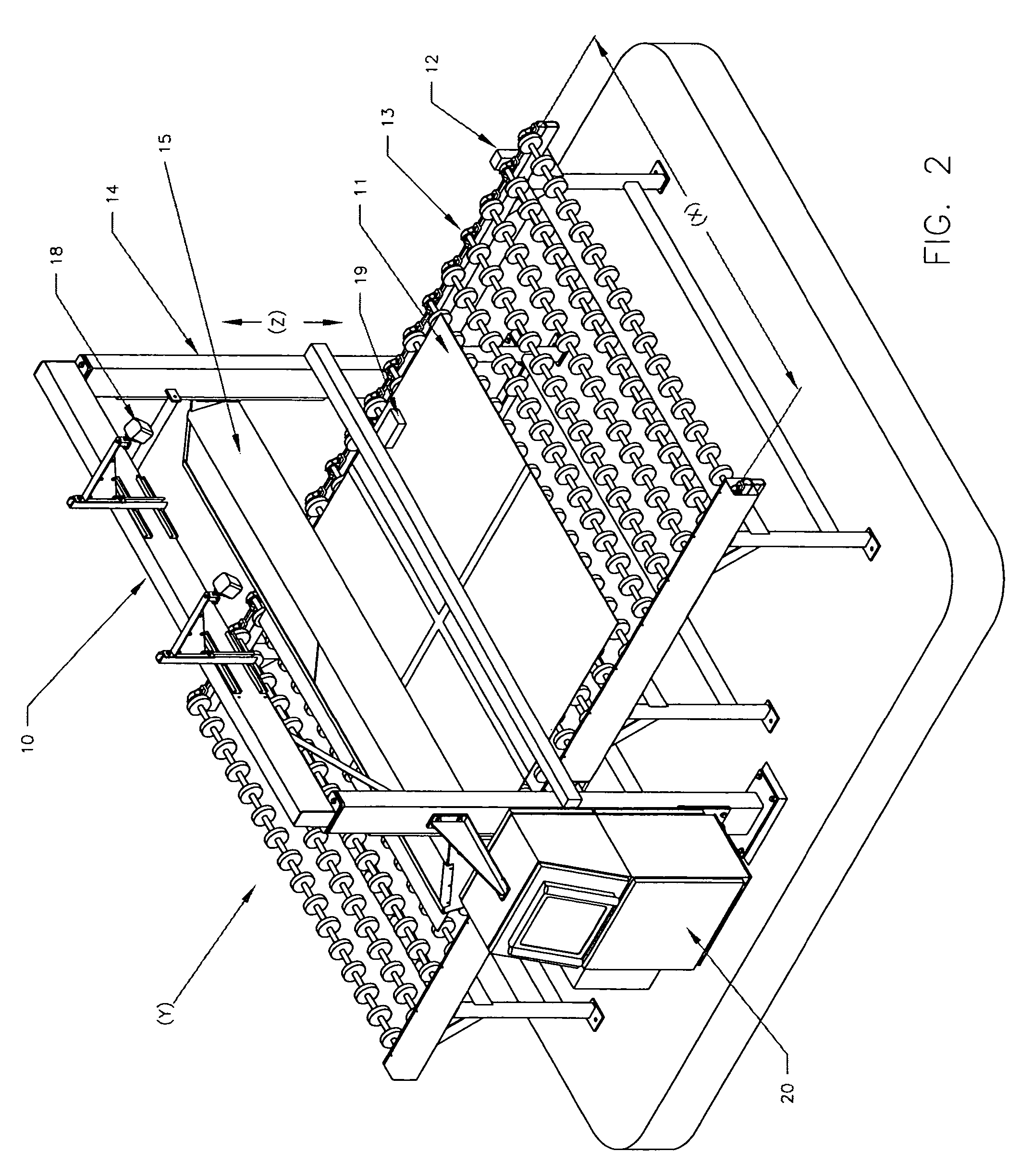
Using a simplifying assumption that distortion is primarily a function of the rollers in the heat-treatment equipment, the industry has limited measurements to address roll wave or corrugation in the glass.
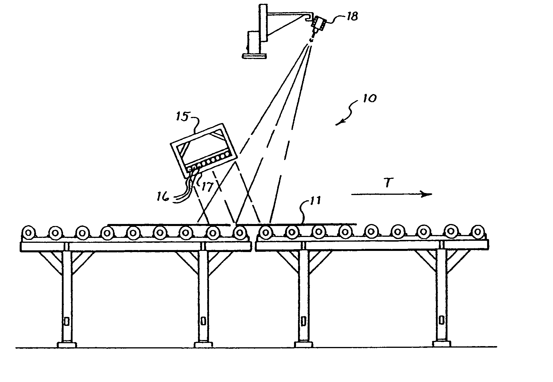
Although roll wave distortion is problematic, local distortion across the glass in directions perpendicular to the transport rollers (x) is also highly problematic.
No practical means exist for measuring these various distortions on a production line.
Current measurement means are limited to measurement of very small samples of glass relative to the volume of glass manufactured on the lines.
Measurements are limited to a small sample, due to the time required to extract a sample from the process and measure with a dial indicator depth gauge over the entire surface of the glass.
Instrumentation is operator dependent with poor repeatability and is prone to error.
Such tests may be destructive, often scratching the surface of the glass as the dial indicator gauge is rolled over the surface.
The dial indicator is not able to measure pocket distortion or micro corrugation due to lack of resolution.
The method is highly accurate but destructive, and impractical for measuring glass from a float or tempering line.
None of the methods in use is able to measure pocket distortion.
Pocket distortion is physically too shallow to be measured using a dial indicator depth gauge, to random to be measured using interferometry, and not able to be quantified using a zebra board.
Operators vary in their quality judgments, and consistent quality control is difficult to achieve.
There is no practical means to consistently measure, quantify and document distortion in large volumes of glass.
There is no practical means to measure pocket distortion and micro corrugation on a production line in real time.
As with U.S. Pat. No. 4,585,343, the device is limited to measuring corrugation in Y and Z directions and relies on the simplifying assumption that the glass is uniformly corrugated transverse to the direction of travel.

Method used


Image

  • Optical system for imaging distortions in moving reflective sheets
  • Optical system for imaging distortions in moving reflective sheets
  • Optical system for imaging distortions in moving reflective sheets

Examples


specific example

[0047]Referring to FIG. 2, there is shown a perspective view of a roller wave measurement system 10 for use in inspecting individual glass sheets 11 which have been treated by a glass tempering system. In FIG. 2, the glass tempering system includes a conventional encoding device, 12 such as a rotary signal detector, detects the movement of the glass on the conveyor based upon the rotation of one of the rollers of a conveyor 13 having a plurality of rollers. The transport direction is indicated by the arrow T, and the conveyor width is indicated by the arrow W. As glass sheets 11 exit the tempering system, the apparatus 10 measures the roller wave distortion in the sheets 11. The apparatus includes a support frame 14 and a light box 15 having a set of light bulbs 16 and a patterned diffuser 17. The light bulbs 16 are high-intensity, high-frequency fluorescent tubular bulbs manufactured by Voltarc or similar, spanning the entire length of the light box 15. The light box 15 length exce...


PUM


Abstract

A method and apparatus for detecting and measuring the optical distortion in pieces of glass and other reflective sheets are disclosed. The method inspects the full length and width of large area glass sheets or multiple sheets comprising a load of glass and uses optical magnification of a reflected circular image of precise size. A plurality of circular images is projected onto the glass and reflect as ellipsoids representative of local surface contours. The major and minor axes of the reflected axis define the axis of greatest magnification and demagnification. Distortions in the glass surface are measured in lens power as localized magnification at the elliptical axis. The angle and magnitude of the minor and major axis of the reflected ellipsoids provide data to map the surface profile of the glass. The method measures distortion of random or periodic frequency and measures distortion in all axes.

Description

CLAIM FOR PRIORITY UNDER 35 U.S.C. §120[0001]This is a continuation-in-part application of application number PCT / US01 / 27280 filed Aug. 30, 2001 which was published in English under PCT Article 21(2), which application claims priority on U.S. Application Ser. No. 60 / 230,281, filed Sep. 1, 2000.FIELD OF THE INVENTION[0002]The present invention relates generally to optical devices, and in particular a method and apparatus for measuring optical distortion in a reflective sheet.BACKGROUND[0003]This invention relates to an optical system for imaging distortions in a moving reflective sheet, such as distortions in glass sheets caused during a tempering process.[0004]When glass sheets are tempered or annealed, they are transported through a heated furnace where they are heated to a critical temperature at which internal stresses are relieved. Achieving the critical temperature in a uniform manner over many square meters is difficult without softening the glass. Typically the glass reaches ...

Claims


Application Information

Patent Timeline
Patent Type & Authority Patents(United States)
IPC IPC(8): H04N7/18G01B11/30
CPCG01B11/306G01N21/896
Inventor ABBOTT, MARK M.HEGSTROM, ERIC
Owner LITESENTRY LLC
Why Eureka
Try Eureka