Continuously tunable RF MEMS capacitor with ultra-wide tuning range

a capacitor and continuous tunable technology, applied in capacitors, mechanically variable capacitor details, electrical apparatuses, etc., can solve the problems of consuming a significant amount of steady-state power, a large amount of resistive loss and relatively high power consumption, and the continuous tuning range of the varactor is sacrificed

Inactive Publication Date: 2008-03-18
HRL LAB
View PDF10 Cites 19 Cited by
  • Summary
  • Abstract
  • Description
  • Claims
  • Application Information

AI Technical Summary

Benefits of technology

[0012]The present continuously tunable RF MEMS varactor features a tunable range of over 4000%. The varactor's innovative design allows for continuous adjustment of the gap between the two plates of the varactor from a maximum distance to zero by electrostatic attraction. The continuous tuning range of prior art, electrostatically actuated, two parallel-electrode systems is limited by the abrupt closing of the air gap occurring as the electrostatic force exceeds the spring force of the beam. However, with the present varactor, by incorporating spring linkages in the cantilever assembly, and by providing a dielectric element to act as a second anchor for the cantilever assembly, the actuation voltage can be increased to well above that necessary to initiate the snap down effect, without sacrificing the continuous tuning range of the varactor.
[0013]A method is provided of continuously varying the capacitance of a MEMS varactor having a cantilever assembly mounted on a base portion, the cantilever assembly having a first capacitance plate and a dielectric element mounted ther

Problems solved by technology

However, solid-state varactors provide a very limited tuning range, usually in the range of 300-400%, have a high resistive loss and relatively high power consumption.
In a solid state varactor diode used to provide a tunable capacitor, the varactor's capacitance is set by a bias current generated by a sub-circuit that can consume a significant amount of steady state power.
Furthermore, the signal current applied to a solid-state varactor may tend to affect the capacitance, thus inducin

Method used


Image

  • Continuously tunable RF MEMS capacitor with ultra-wide tuning range
  • Continuously tunable RF MEMS capacitor with ultra-wide tuning range
  • Continuously tunable RF MEMS capacitor with ultra-wide tuning range

Examples


Embodiment Construction

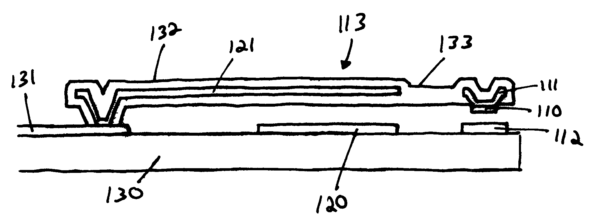
[0023]FIG. 1 shows a cross-sectional view of an embodiment of the present varactor having a base portion 130 supporting a mounting portion 131, a first actuation electrode 120 and an RF line electrode 112. The mounting portion 131 in turn serves to support a cantilever assembly 113. The cantilever assembly 113 includes a dimple 111 positioned at the free end of the cantilever assembly 113. This dimple 111 and the RF line electrode 112 are designed to function together as a pair of capacitance plates.

[0024]A second actuation electrode 121 is included in the cantilever assembly 113 which, when used together with the first actuation electrode 120, allows the cantilever assembly 113 to be pulled towards the base portion 130. The strength of the pull is dependent on the voltage applied across the first and second actuation electrodes. In the varactor shown in FIG. 1, a control circuit (not shown) applies a voltage Vc across the varactor's first and second actuation electrodes generating ...


PUM


Abstract

A method is provided of continuously varying the capacitance of a MEMS varactor having a cantilever assembly mounted on a base portion, the cantilever assembly having a first capacitance plate and a dielectric element mounted thereon, and the base portion having a second capacitance plate mounted thereon. The method includes applying a first actuation voltage to deform the cantilever assembly until the dielectric element contacts the second capacitance plate leaving a gap therebetween, and applying a second actuation voltage larger than the first actuation voltage to further deform the cantilever assembly to reduce the gap between the dielectric element and the second capacitance plate.

Description

FIELD OF THE INVENTION[0001]This invention relates to trimmable and continuously tunable capacitors and more specifically to a tunable-trimmable Micro Electro-Mechanical System (“MEMS”) capacitor having an ultra-wide tuning range.BACKGROUND OF THE INVENTION[0002]Tunable capacitors are widely employed in radio frequency (“RF”) communication applications as low noise parametric amplifiers, harmonic frequency generators, frequency controllers such as voltage-controlled oscillators, filters and tunable high impedance surfaces. Various devices would benefit from tunable capacitors or varactors having a wide tuning range, low loss and a low power consumption. A useful varactor should also be capable of being monolithically integrated in the device in which it is employed.[0003]Typically, solid-state varactors are employed where tunable capacitance is required. However, solid-state varactors provide a very limited tuning range, usually in the range of 300-400%, have a high resistive loss a...

Claims


Application Information

Patent Timeline
IPC IPC(8): H01G5/00
CPCH01G5/18
Inventor HSU, TSUNG-YUANCHANG, DAVID
Owner HRL LAB
Why Eureka
Try Eureka