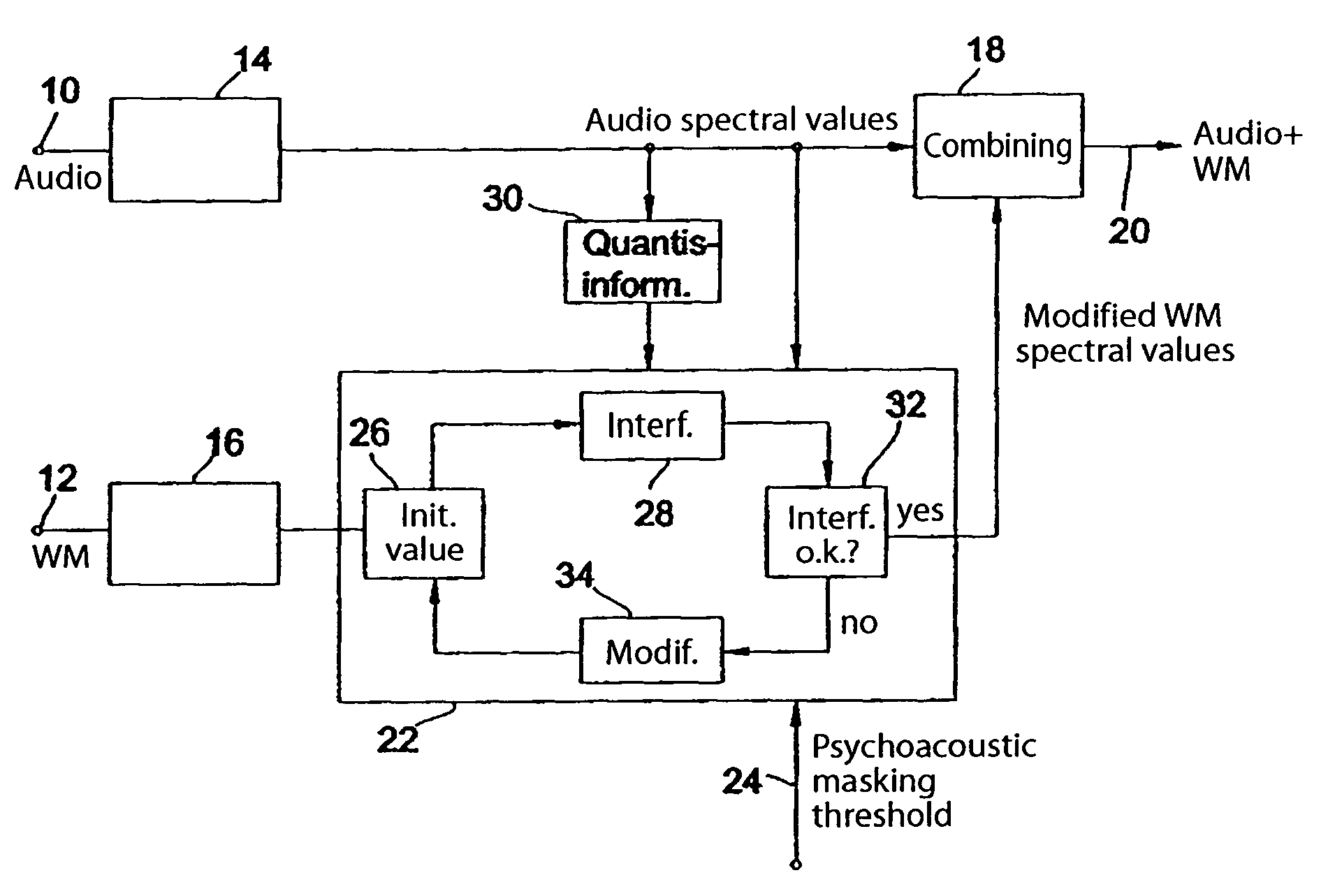
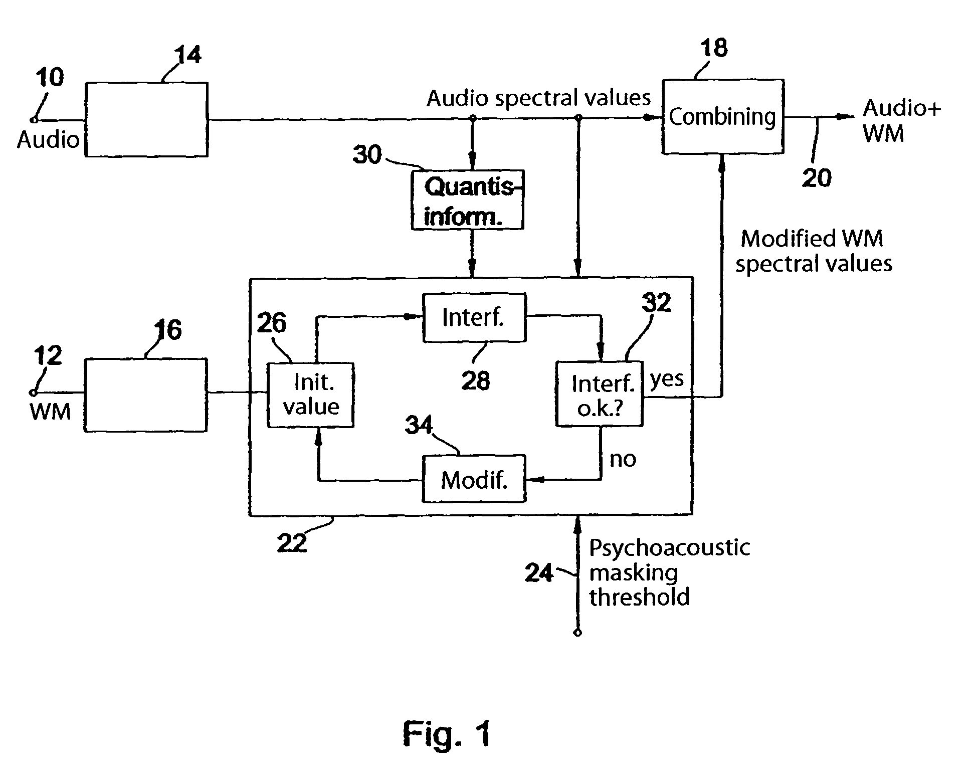
Device and method for embedding a watermark in an audio signal

Active Publication Date: 2008-03-18
FRAUNHOFER GESELLSCHAFT ZUR FOERDERUNG DER ANGEWANDTEN FORSCHUNG EV
View PDF12 Cites 65 Cited by
  • Summary
  • Abstract
  • Description
  • Claims
  • Application Information

AI Technical Summary

Benefits of technology

[0024]An advantage of the present invention is that conditions which in the final analysis do not correspond to the output conditions, namely the audio signal/watermark conditions prior to quantization, are no longer considered. Instead, the watermark is modified progressively, e.g. by iteration, until a desired watermark “interference energy” is found. In accordance with the present invention the conditions which pertain after the quantizer, i.e. the conditions which are most important for the audio signal decoder and for the watermark extractor, are now taken into account.
[0025]Although in the prior art the watermark energy was normally set to a value which is smaller than or equal to the psychoacoustic masking threshold, the problem remained as to what happens to the watermark signal during quantization. As has been explained, it might be that the watermark signal is quantized out, with the result that either no watermark or only a very weak watermark could be extracted from the decoded signal. What might also happen is that the interference which is introduced by the watermark was audible in the decoded signal despite the watermark having been so weighted that it falls below the masking threshold.
[0026]In accordance with the present invention precise control is now achieved as a result of the processing of the watermark on the basis of the conditions pertaining after quantization. This control has the advantage that not only can it be ensured on the one hand that the watermark causes either no or only minimally audible interference, but also that adequate watermark detectability can be guaranteed at the same time. Furthermore, the method according to the present invention also provides the advantage that, in cases where good detectability is particularly important, a certain degree of—tolerable—interference can be deliberately introduced into the audio signal in the interests of a higher watermark detectabilit

Problems solved by technology

If the quantization noise introduced by the quantizer should exceed the psychoacoustic masking threshold, the decoded audio signal will contain audible interference.
It should be noted that the coding method used here entails loss since quantization has been performed in the encoder.
On the other hand, if the quantization steps are too big, so too will be the quantization noise, which can manifest itself as audible interference in the decoded signal.
Audio signal sections with good masking properties can then be encoded with a relatively small bit outlay, whereas audio signal sections with relatively poor masking properties, such as e.g. tonal audio signal sections, must be quantized very finely, which means that a large number of bits must be expended in order to encode these audio signal sections.
Although encoding with constant quality—and thus with a variable bit rate—is attractive as regards data efficiency on the one hand and audio quality on the other, this concept is disadvantageous in that it is only suitable for applications which support a variable transmission rate, such as e.g. the storage of compressed audio signals or the transmission of compressed audio signals over packet-based networks, e.g. the internet.
In particular, depending on the bit rate, it may happen that sections of the audio signal which have relatively poor masking properties cannot be quantized finely enough, i.e. are under-encoded, and may contain

Method used


Image

  • Device and method for embedding a watermark in an audio signal
  • Device and method for embedding a watermark in an audio signal
  • Device and method for embedding a watermark in an audio signal

Examples


Embodiment Construction

[0035]The device according to the present invention shown in FIG. 1 has an audio input 10 and a watermark input 12. Both the audio signal at the audio input 10 and the watermark signal at the watermark input 12 are transformed into a spectral representation by units 14 and 16 respectively. The spectral representation of the audio signal comprises audio spectral values, whereas the spectral representation of the watermark signal comprises watermark spectral values. The audio spectral values are combined with modified watermark spectral values in a unit 18 for combining to provide the combined audio signal with embedded watermark at an output 20. According to the present invention a unit 22 for processing the spectral representation of the watermark signal in accordance with a psychoacoustic masking threshold supplied via an input 24 is provided for this purpose. The spectral representation of the watermark signal is processed according to the psychoacoustic masking threshold received...


PUM


Abstract

Prior to embedding a watermark in an audio signal, a spectral representation of the audio signal and a spectral representation of the watermark signal are determined. The spectral representation of the watermark signal is then processed on the basis of a psychoacoustic masking threshold of the audio signal. The processed watermark signal is combined with the audio signal to obtain an audio signal bearing a watermark. The spectral representation of the watermark signal is processed iteratively as follows: first a predetermined watermark initial value is selected, then the interference introduced into the spectral representation of the audio signal after a quantization of the spectral representation of the audio signal is determined and then, if the interference introduced by the watermark initial value exceeds the predetermined interference threshold, the watermark initial value is modified progressively until the resulting interference introduced into the spectral representation of the audio signal after quantization is less than or equal to the predetermined interference threshold. The modified watermark initial value at the end of the iteration is used as the processed watermark signal to be combined with the audio signal. As a result it is no longer possible for a watermark to be quantized out. Instead, full control over the energy of the watermark is achieved. A watermark can therefore be embedded in an audio signal to provide either the best possible degree of watermark detectability or the best possible audio quality.

Description

FIELD OF THE INVENTION[0001]The present invention relates to the field of audiocoding and in particular to methods and devices for embedding a watermark in an audio signal.BACKGROUND OF THE INVENTION AND PRIOR ART[0002]Modern audiocoding methods process time-discrete audio sampled values to generate a bit stream which is compressed in relation to the original audio signal. The stream of time-discrete audio sampled values is first windowed so as to generate successive blocks of windowed audio sampled values from the stream of audio sampled values. The additional processing takes place blockwise. A block of audio sampled values generated by windowing is typically converted into a spectral representation by means of an analysis filter bank. The spectral representation comprises neighbouring frequency spectral values from the frequency 0 to the maximum audio frequency, which may e.g. be 16 kHz. The audio spectral values are grouped into scale factor bands and quantized. The quantization...

Claims


Application Information

Patent Timeline
IPC IPC(8): G10L11/00H04L9/00G10L19/018G10L19/02G11B20/00
CPCG10L19/018G10L19/02
Inventor HERRE, JURGENKULESSA, RALPHNEUBAUER, CHRISTIANSIEBENHAAR, FRANK
Owner FRAUNHOFER GESELLSCHAFT ZUR FOERDERUNG DER ANGEWANDTEN FORSCHUNG EV
Why Eureka
Try Eureka