Internal combustion engine comprising an engine braking arrangement

a technology of internal combustion engine and braking arrangement, which is applied in the direction of machines/engines, output power, transportation and packaging, etc., can solve the problems of loss of exhaust gas energy, reduce the rotational speed of the exhaust gas turbocharger, and reduce the difference in pressure

Inactive Publication Date: 2008-03-25
DAIMLER AG
View PDF14 Cites 36 Cited by
  • Summary
  • Abstract
  • Description
  • Claims
  • Application Information

AI Technical Summary

Benefits of technology

[0009]Preferably, the bypass device is a rotary slide valve. The advantage of the use of a rotary slide as bypass device resides in low operating forces required even at high exhaust gas pressures.
[0010]In a further refinement of the invention, the rotary slide valve has a housing with a tubular duct which is placed therein and in which a freely rotatable rotor is mounted which has a circular sector-shaped cross section. The housing has an opening to the exhaust pipe, an opening to the bypass pipe and an opening to an exhaust pipe through which the exhaust gas can be discharged to the atmosphere or into an exhaust system. The duct permits the exhaust pipe and the bypass pipe to be placed into communication with the exhaust pipe. The circular sector-shaped cross-section of the valve rotor is selected in such a manner that the rotor can either completely close the exhaust pipe and the bypass duct or just the exhaust pipe or can close the exhaust pipe completely and the bypass pipe partially. The advantage resides in the simple, pressure insensitive and gastight construction even at high exhaust gas pressures.
[0011]In a further refinement of the invention, the circular sector-shaped cross section of the valve rotor has a circular sector angle of 120° to 140°. The selection of this circular sector angle makes it possible to realize a flat, construction-space-saving construction of the housing and of the connected pipes.
[0012]In a particular embodiment of the invention, the compression brake opens in the engine braking mode and the bypass device closes the exhaust pipe and the bypass pipe at low to medium rotational speeds of the internal combustion engine in the engine braking mode. The compression brake is preferably designed in the form of a known constant throttle. The constant throttle is an additional throttle valve in the cylinder head that can be opened continuously in the engine braking mode. The throttle valve opens or closes a bypass around an outlet valve of a cylinder of the internal combustion engine, so that compressed air passes into the exhaust tract. In the engine braking mode, the constant throttle opens and releases at least some of the compressed gas. In addition, the bypass device closes the exhaust pipe and the bypass pipe in the engine braking mode. As a result, the pumping power of the internal combustion engine is additionally increased. The advantage of the use of a constant throttle with the bypass device as an airbrake resides in the increased braking power at low to medium rotational speeds of the internal combustion engine. In addition, a brake flap can be omitted in the exhaust system.
[0015]In a further refinement of the invention, in the engine braking mode, the outlet valves of the internal combustion engine can be briefly opened by pressure peaks of the exhaust gas in the exhaust tract, as a result of which exhaust gas passes from the exhaust tract into the cylinders of the internal combustion engine. The short opening of the outlet valves is possible in particular at low cylinder pressures. In particular at the end of the first working stroke (intake) or at the beginning of the second working stroke (compression), this leads to a recharging effect, in which exhaust gas passes out of the exhaust tract into the cylinders of the internal combustion engine. The recharging effect advantageously leads to an increased filling of cylinders and therefore to an increased engine braking power.

Problems solved by technology

For example, if a bypass pipe is not closed in a gastight manner in the combustion mode, exhaust gas energy is lost, since this energy is no longer available to the power turbine driven by exhaust gas via the opened exhaust pipe.

Method used


Image

  • Internal combustion engine comprising an engine braking arrangement
  • Internal combustion engine comprising an engine braking arrangement
  • Internal combustion engine comprising an engine braking arrangement

Examples


Embodiment Construction

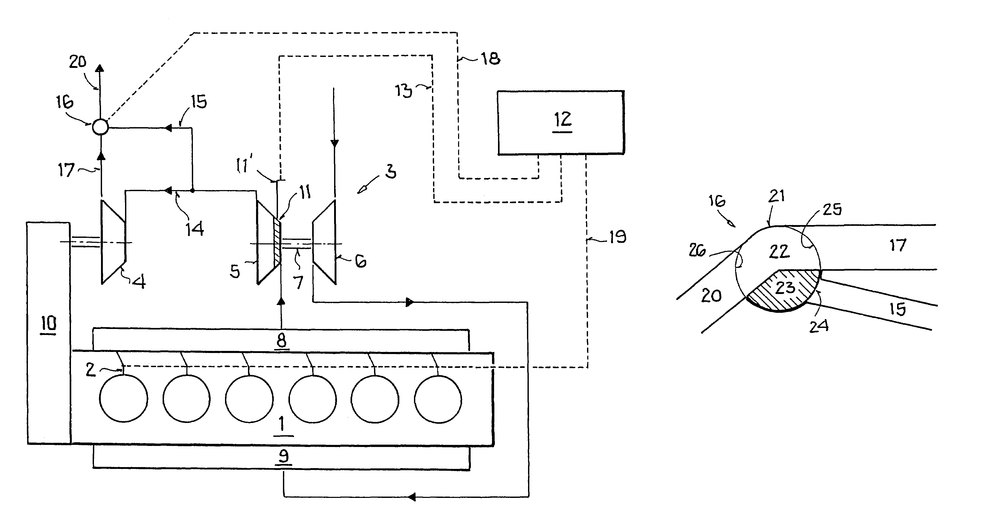
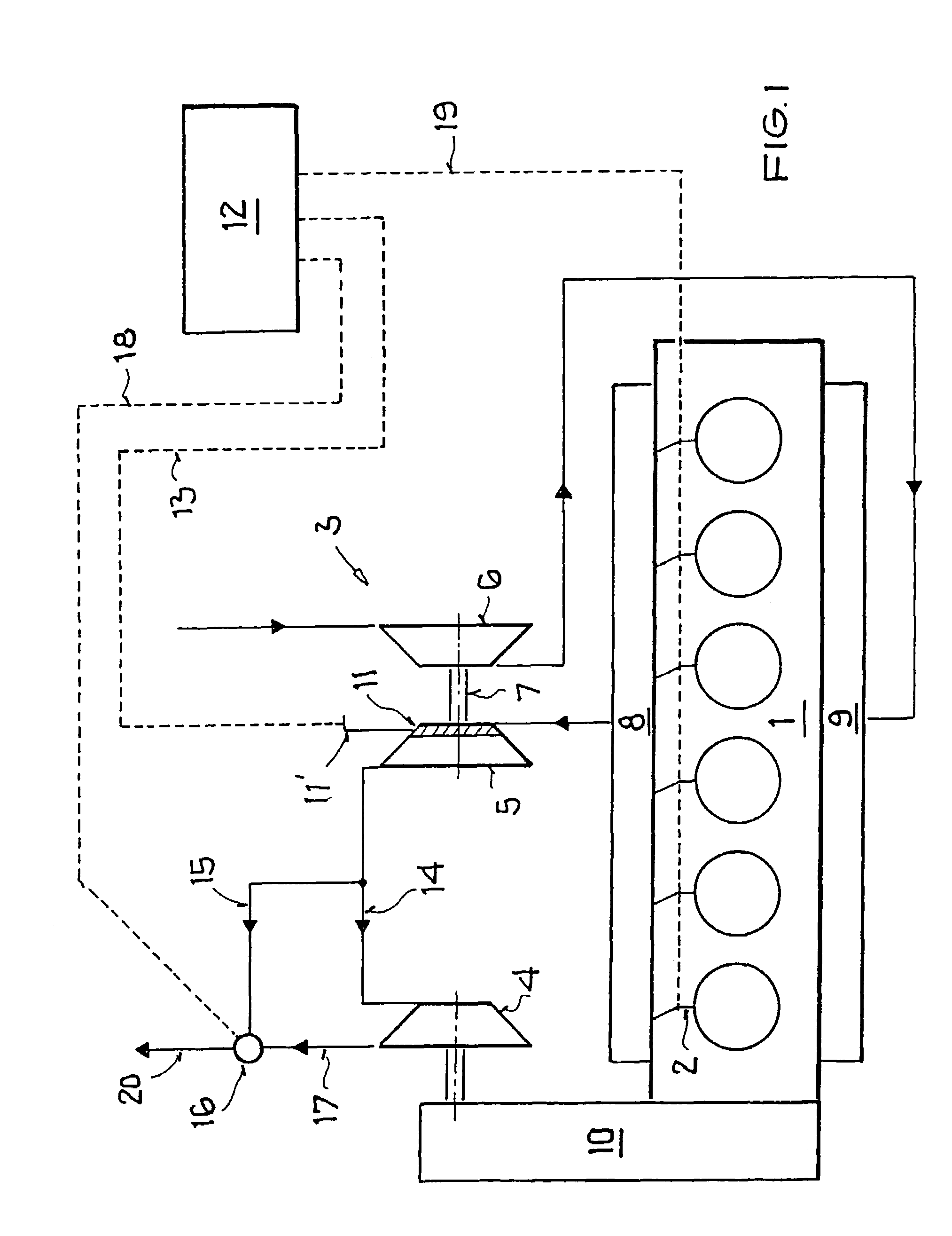
[0022]FIG. 1 illustrates, in diagrammatically simplified form, an internal combustion engine 1 with at least one outlet valve per cylinder, the internal combustion engine being equipped with an engine braking mechanism including a constant throttle 2, with an exhaust gas turbocharger 3 and a power turbine 4. The engine braking mechanism 2 is in the form of a known compression brake, preferably as a constant throttle. For the construction and the manner of operation of the constant throttle, reference is made by way of example to DE 197 27 584 C1. The exhaust gas turbocharger 3 has an exhaust gas turbine 5 and a compressor 6 which are connected to each other via a common shaft 7. The exhaust gas turbine 5 is connected to an exhaust tract 8 and the compressor 6 is connected to an intake tract 9 of the internal combustion engine 1. A charge air cooler (not illustrated specifically) can be placed in the intake tract 9. The power turbine 4 is provided downstream of the exhaust gas turbin...


PUM


Abstract

In an internal combustion engine comprising an engine braking arrangement including a constant throttle valve, an exhaust gas turbocharger with a variable turbine guide vane structure and a power turbine connected to an exhaust tract and a compressor connected to an intake tract of the internal combustion engine, the power turbine is disposed in the exhaust duct downstream of the exhaust gas turbine and is driven by the exhaust gas of the internal combustion engine and a bypass device is provided in a bypass pipe which extends around the power turbine and via which the exhaust pipe can be completely closed and the bypass pipe can be completely or partially closed so as to selectively partially or completely block the exhaust gas flow and the bypass flow to an exhaust gas discharge pipe.

Description

[0001]This is a Continuation-In-Part Application of International Application PCT / EP2004 / 008978 filed 11 Aug. 2004 and claiming the priority of German application 103 39 857.0 filed 29 Aug. 2003.BACKGROUND OF THE INVENTION[0002]The invention relates to an internal combustion engine comprising an engine braking arrangement in the form of a compression brake.[0003]Patent Specification EP 0 477 579 B1 discloses such an internal combustion engine comprising an engine braking arrangement in the form of a compression brake. The internal combustion engine has an exhaust gas turbocharger, the exhaust gas turbine of which is disposed in an exhaust tract, and the compressor of which is disposed in an intake tract of the internal combustion engine. A power turbine which is driven by the exhaust gas of the internal combustion engine and is coupled to the internal combustion engine via a transmission is provided downstream of the exhaust gas turbine. A bypass device including a bypass pipe which...

Claims


Application Information

Patent Timeline
Patent Type & Authority Patents(United States)
IPC IPC(8): F02G3/00F02B37/00F02B41/10F16K11/085F02D29/00F02D9/06F02B37/22F02B37/24
CPCF02B37/005F02B37/24F02B41/10F02D13/04F01L13/06F01L13/065F02B37/22Y02T10/144Y02T10/163Y02T10/12Y10T137/86871
Inventor ALBAT, RAINER
Owner DAIMLER AG
Why Eureka
Try Eureka