Drilling device

a drilling device and drilling technology, applied in the direction of portability drilling machines, turning machine accessories, manufacturing tools, etc., can solve the problems of high consumption costs, need for a tool with a threaded shaft, and so as to reduce the risk of tool tilting, and ensure the effect of safety

Inactive Publication Date: 2008-03-25
AIRBUS OPERATIONS GMBH
View PDF26 Cites 20 Cited by
  • Summary
  • Abstract
  • Description
  • Claims
  • Application Information

AI Technical Summary

Benefits of technology

[0029]Thus, a typical case of application can be seen in aircraft construction and aircraft assembly for producing rivet holes. In this case, work would take place with materials whose dusts arising during drilling work are hazardous to health (e.g. CFRP, FRP, Glare), metallic materials (e.g. aluminium, titanium, steel), as well as composites of said materials. It emerges precisely in manual drilling work with high-strength materials such as titanium, for example, that the drilling device, through the damping and the associated uniform feed motion, contributes towards greatly reduced wear of hard-metal tools due to forced breakages and forced chipping. Furthermore, the device can be used to advantage in the machining of brittle materials (e.g. chipboard, gypsum, glass) in order to avoid chips at the edges of holes.
[0044]In order to minimise the risk of injury, it is possible to provide a protective casing in the drill chuck.

Problems solved by technology

Drawbacks of the devices are the usually long construction (the risk of tilting of the tool therefore exists despite the pendulum shaft) and the need for a tool with a threaded shaft (high consumption costs).
Furthermore, no damping and no suction-type extraction is included with these devices.
Furthermore, this device does not include any damping.
Moreover, expensive hardened drill bushes and very long tools (>120 mm) are required.
Finally, a high noise level is generated by the suction-type extraction.
All of the mentioned devices are unable to provide simultaneously guidance of the tool (guarantee of roundness, cylindricity and squareness), a depth stop, damping and suction-type extraction with a manual machining process.
Essential problems of manual drilling with the known devices that need to be solved arise on account of the unregulated feed.
Furthermore, on account of the manually controlled feed in the manual process, the tool has a tendency to become screwed at the tool exit through the material.
This in turn often leads to tool breakages, precisely in the case of small tool diameters.
Apart from the unregulated feed, hand-guided machining is a further problem, as a result of which non-round holes, with which the required tolerances are not met, can arise.
Furthermore, the manual guidance can lead to non-compliance with the squareness of the hole to the workpiece surface.
Chips and dusts generally arise during the cutting of materials, as a result of which the use of suction-type extraction may be required, in particular in the case of dusts hazardous to health.
This can however lead to high noise levels if the geometry of the suction-type extraction device is not designed in the optimum manner.
Furthermore, some drilling devices require long tools, and this in turn leads to high consumption costs.
In addition, expensive hardened drill bushes are usually required to guide the tools.
A further important critical point is the fact that the stroke, or more precisely the adjustment range, of the existing devices is too small and too inflexible for some tasks and usually there is not a good view of the machining point.
However, since the machining of, for example, derived timber products and plastics is also possible with the device, other areas of application for the present drilling device lie in the building trade and the shipbuilding industry, in the furniture industry, the wind-energy industry, in the do-it-yourself sector and in general handicraft work, because here too there is the problem of the screwing-through of tools at the tool exit through the material and the formation of chips and dusts which have to be extracted by suction.
It is not desirable here for the feeding force raised due to damping to be effective over the whole displacement movement, because the physical burden on the worker would thus be greatly increased.

Method used


Image

  • Drilling device
  • Drilling device
  • Drilling device

Examples


Embodiment Construction

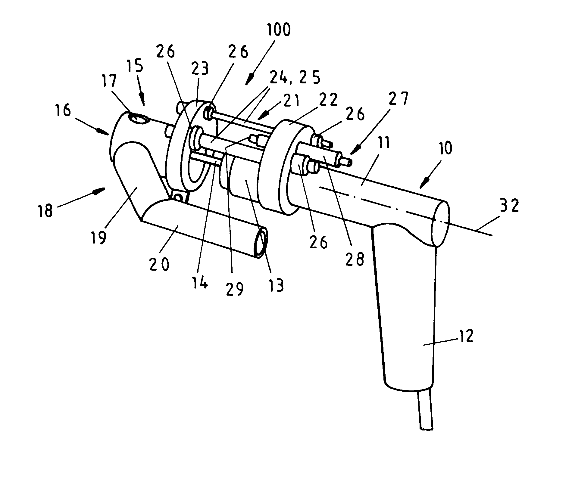
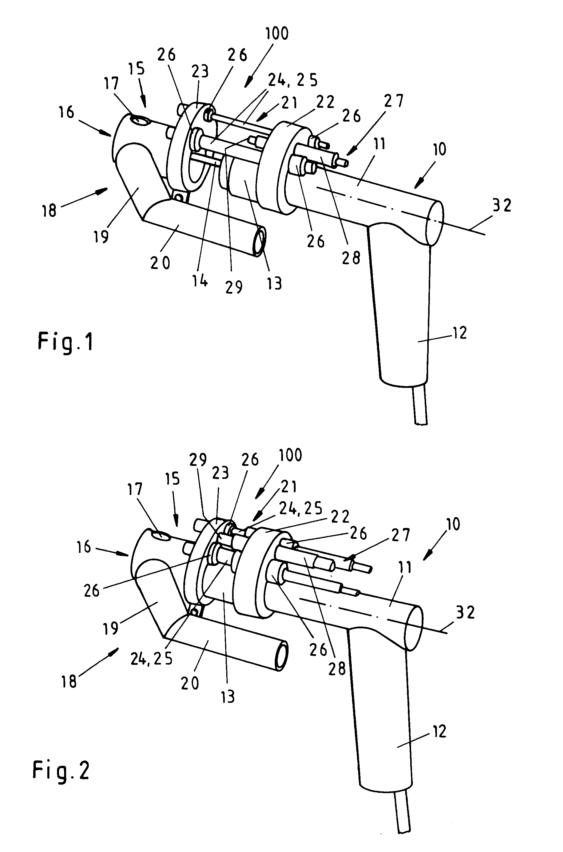
[0059]FIGS. 1 and 2 show an example of embodiment of a device 100, which is arranged on a drilling machine 10. This is a drilling machine 10 known per se for manual drilling, which in the usual way has a casing 11, a grip 12 and a tool chuck 13 for a tool 14.

[0060]Device 100 consists of a workpiece jigging device 15, with a contact surface 16, which can have contact feet not shown in FIGS. 1 and 2. An opening 17 is made in workpiece jigging device 15 in order to be able to see the action point of tool 14. Also arranged on workpiece jigging device 15 is suction-type extraction device 18, which enables material chips, dusts and impurities to be conveyed via suction pipe 19 out of the area of the workpiece jigging device, or more precisely the machining or action point. For this purpose, suction pipe 19 is provided with a connection piece 20, to which a tube (not shown) can be connected. In the form of embodiment shown in FIGS. 1 and 2, connection piece 20 is led parallel to the machin...


PUM

PropertyMeasurementUnit
displacementaaaaaaaaaa
areaaaaaaaaaaa
depthaaaaaaaaaa

Abstract

In order to improve a device (100) for a drilling machine (10) known per se for manual drilling with a casing (11), a grip (12), a tool chuck (13) and a tool (14), especially a drilling, reaming or counterboring tool, in such a way that manual drilling can be carried out with optimum conditions, it is proposed that the device comprises aworkpiece jigging device (15) with at least one contact face anda guide device (21) for the parallel guidance of the tool (14) and / or of the casing (11) when there is a displacement of the workpiece jigging device (15) relative to the casing (11), said displacement being coaxial with a machine axis and / or tool axis, anda suction-type extraction device (18) for conveying away and sucking away material chips, dusts and impurities from the area of the workpiece jigging device (15), or more precisely the machining point anda control device (27) for the control of the feed motion between the workpiece jigging device (15) and the casing (11), said control being active at least in sections along the path.

Description

TECHNICAL FIELD[0001]The invention relates to a device according to the preamble of claim 1.PRIOR ART[0002]Devices are known for the suction-type extraction of chips and dusts arising during drilling, either adapted to the drilling machine (machine tool or manual drilling machine) or as a separate component (e.g. DE 4313658 C1, DE 2715378 C2, DE 3340090 A1, DE 4038941 C2, DE 10000015 A1, DE 3605204 A1, DE 3835582 A1, DD 19860182 C2).[0003]Devices are known that provide a depth stop during manual drilling, either adapted to the drilling machine or as a separate component (e.g. DE 7724047 U1, AT 350778 B).[0004]Devices are known that dampen the feed motion during manual drilling, either adapted to the drilling machine or as a separate component (e.g. DE 19639122 A1).[0005]Devices are known that provide a depth stop and suction-type extraction of chips and dusts arising during the drilling process, either adapted to the drilling machine or as a separate component (e.g. DE 3509199 C2).[...

Claims


Application Information

Patent Timeline
Patent Type & Authority Patents(United States)
IPC IPC(8): B23B47/00B23B45/00B23B49/00B23Q11/00
CPCB23B49/008B23Q11/0046Y10S408/712B23B2222/88B23B2226/45B23B2228/36B23B2250/16B23B2260/136B23B2270/62Y10T408/6757Y10T408/5653Y10T408/76Y10T408/56245Y10T408/50B23B2222/28
Inventor HINTZE, WOLFGANGCLAUSEN, ROLFPLUCINSKI, MARTINSTOVER, ENNOMEI.BETA.NER, FRIEDRICH
Owner AIRBUS OPERATIONS GMBH
Why Eureka
Try Eureka