Mechanically robust lead frame assembly for an electrical connector

a lead frame and electrical connector technology, applied in the direction of electrical apparatus, coupling device connection, coupling protective earth/shielding arrangement, etc., can solve the problem that the connector cannot be easily installed using standard flat rock tooling, and achieve the effect of adding mechanical strength and robustness

Active Publication Date: 2008-03-25
FCI AMERICAS TECH LLC
View PDF13 Cites 62 Cited by
  • Summary
  • Abstract
  • Description
  • Claims
  • Application Information

AI Technical Summary

Benefits of technology

[0004]The present invention, through the arrangement of solid and air dielectrics, may allow standard flat rock tooling to be used to install the connector on a PCB. A lead frame assembly is disclosed in which holes are formed in one or more contacts of the assembly. A dielectric material, such as plastic, may be formed along a length of the contact and may be secured to the contact by filling the holes. The dielectric material may span across two or more contacts of the lead frame assembly and also across gaps between the contacts. In alternative embodiments, the dielectric material may span across an entire side of a lead frame assembly. The dielectric material may add mechanical strength and robustness to the lead frame assembly and thus to the connector. In alternative embodiments, the dielectric material may abut one side of one or more contacts in the lead frame assembly and not fill or otherwise enter any gap located between contacts. In this way, the dielectric material may not affect any edge-coupling of contacts that form differential signal pairs. In further embodiments, the dielectric material abuts opposing sides of the contact, also without entering any gap between contacts. For example, the dielectric material may be formed along a length of a contact, may fill a hole formed in the contact, and may additionally form a retaining cap (e.g., a mushroom or button cap) on the opposing side of the contact. The retaining cap may help hold the dielectric material to the contact or to the lead frame assembly.

Problems solved by technology

However, such a connector may not be readily installed using standard flat rock tooling.

Method used


Image

  • Mechanically robust lead frame assembly for an electrical connector
  • Mechanically robust lead frame assembly for an electrical connector
  • Mechanically robust lead frame assembly for an electrical connector

Examples


Embodiment Construction

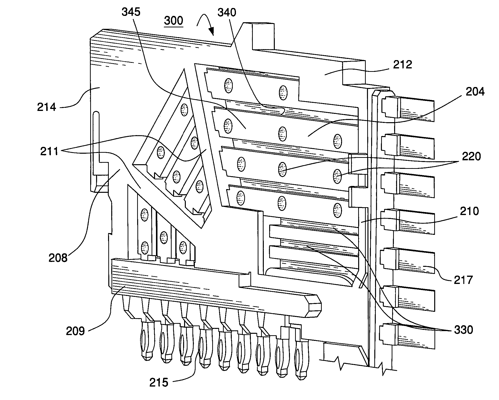
[0009]FIG. 3 is a perspective view of an example lead frame assembly 200. The lead frame assembly 200 includes a lead frame housing 208. The lead frame housing 208 may be made of a dielectric material such as plastic. The lead frame housing 208 may be made by insert molding or by any other suitable method. The lead frame housing 208 may include a terminal frame component 209 and a mating frame component 210. The lead frame housing 208 additionally may include supporting frames 211 that extend across a middle cavity of the lead frame housing 208. The lead frame housing 208 additionally may include a top frame 212 and a back frame 214 that, along with the terminal frame component 209 and the mating frame component 210 define a perimeter of the lead frame housing 208.

[0010]The lead frame assembly 200 may include any number of contacts 204. The contacts 204 may be signal contacts used in either single-ended or differential transmission. In alternative embodiments, the contacts 204 also ...


PUM


Abstract

A lead frame assembly is disclosed in which holes may be formed in contacts of the assembly and a dielectric material extends along a length of the contact. The dielectric material may be further secured to the contact by filling the hole. The dielectric material may span across two or more contacts of the lead frame assembly and also across gaps formed between the contacts, or may span across an entire side of a lead frame assembly. The dielectric material may add mechanical strength and robustness to the lead frame assembly while helping to reduce dust accumulation on electrical contacts of the assembly. The dielectric material may abut only one side of one or more contacts in the lead frame assembly and thus may not affect edge-coupling effect of contacts that form differential signal pairs.

Description

CROSS-REFERENCE TO RELATED APPLICATIONS[0001]The subject matter disclosed in this patent application is related to the subject matter disclosed and claimed in U.S. patent application Ser. No. 11 / 087,047, filed Mar. 22, 2005, now U.S. Pat. No. 6,988,902 which is a continuation of U.S. patent application Ser. No. 10 / 294,966, filed on Nov. 14, 2002, now U.S. Pat. No. 6,976,886 which is a continuation-in-part of U.S. Pat. Nos. 6,652,318 and 6,692,272. The contents of each of the above-referenced U.S. patents and patent applications are herein incorporated by reference in their entireties.FIELD OF THE INVENTION[0002]The invention relates to electrical connectors. More particularly, the invention relates to a mechanically robust lead frame assembly for electrical connectors.BACKGROUND OF THE INVENTION[0003]An electrical connector such as the electrical connector 50 shown in FIG. 1 may include a housing 55 and one or more modular lead frame assemblies 100. The lead frame assembly 100 is al...

Claims


Application Information

Patent Timeline
Patent Type & Authority Patents(United States)
IPC IPC(8): H01R13/405
CPCH01R13/514H01R13/518
Inventor MINICH, STEVEN E.
Owner FCI AMERICAS TECH LLC
Why Eureka
Try Eureka