IOL insertion apparatus and method for making and using same

a technology of iol and insertion tube, which is applied in the direction of coating, intraocular lens, plasma technique, etc., can solve the problems of limiting the size of the inserter tube, difficult, if not impossible, and difficult distal end, so as to improve the lubricity and facilitate practice , effective and reliable lubricity properties

Inactive Publication Date: 2008-03-25
JOHNSON & JOHNSON SURGICAL VISION INC
View PDF47 Cites 63 Cited by
  • Summary
  • Abstract
  • Description
  • Claims
  • Application Information

AI Technical Summary

Benefits of technology

[0010]New apparatus for injecting IOLs and methods for making and using such apparatus have been discovered. The present apparatus achieve enhanced lubricity, thus providing for the use of effective, reliable and non-excessive amounts of force to inject a folded IOL into an eye. The present IOL inserter production methods provide inserters which have very effective and reliable lubricity properties. The present invention is easy to practice. The methods of use included in the present invention often involve surgical techniques which are well practiced and conventionally used to insert IOLs into eyes.
[0011]In general, the present invention involves apparatus for inserting IOLs into an eye which include a lubricity enhancing component physically secured to the apparatus and concentrated at or near the interior wall or walls of the apparatus, for example, at or near the interior wall of the apparatus defining a hollow space through which an IOL is passed. It has been found that the inclusion of such a physically secured or bonded lubricity enhancing component is effective to facilitate the passage of the IOL through the apparatus. Physically securing or bonding such lubricity enhancing components in or on the apparatus is particularly effective since the amount of such component present, and the degree of enhanced lubricity obtained, is conveniently controlled and stable on a long term basis, for example, the apparatus has a relatively long shelf life before use. Preferably, a reduced amount of the physically secured or bonded lubricity enhancing component passes into the eye during use of the present apparatus relative to a similar or substantially identical apparatus on which the lubricity enhancing component is not bonded or secured to the apparatus.
[0012]In one embodiment, the present apparatus include an interior wall which is a plasma-exposed interior wall. This plasma-exposed interior wall preferably has an enhanced ability to physically secure or bond the lubricity enhancing component relative to a substantially identical interior wall which is not plasma-exposed. In one useful embodiment, the plasma-exposed interior wall facilitates forming the lubricity enhancing component concentrated at or near the interior wall of the hollow tube.

Problems solved by technology

Such “distal loading” systems often disadvantageously include a space consuming loading component at or near the distal end of the system which causes the distal end to be relatively large.
This relatively large distal end makes inserting the IOL through a small incision more difficult, if not impossible.
However, whether using a distal loading or proximal loading system, one factor which limits the size of the inserter tube involves the inserter tube itself.
For example, the material from which the inserter tube is made, for example, polypropylene and the like polymeric materials, may not be compatible or otherwise susceptible to causing optics, for example, made from silicone polymeric materials, to pass through relatively small hollow spaces.
For example, the injector tubes may be made of materials, in particular polymeric materials, which have insufficient lubricity to facilitate the passage of a folded IOL through the tube.
In addition, if one were to use a small diameter tube to pass the IOL, excessive force might be needed to pass the IOL through the small hollow space thereby increasing the risks of damaging the IOL and, in extreme cases, even damaging the eye into which the IOL is placed.
However, such lubricity agents in and of themselves occupy valuable space, thereby at least partially defeating the purpose of using such agents Also, such lubricity agents often end up in the eye, thereby creating the risk of causing trauma and / or irritation and / or damage to the eye.

Method used


Image

  • IOL insertion apparatus and method for making and using same
  • IOL insertion apparatus and method for making and using same

Examples


Embodiment Construction

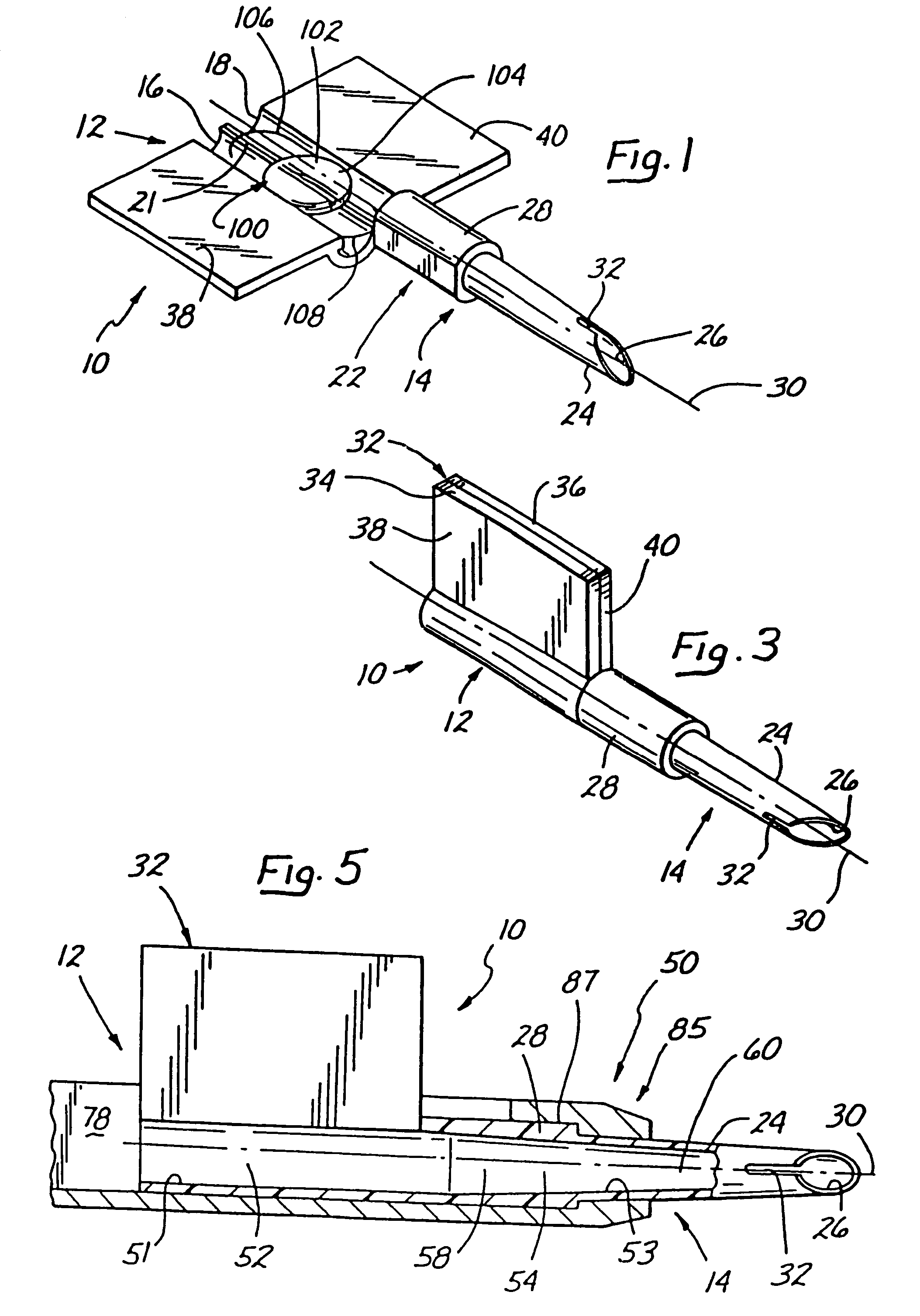
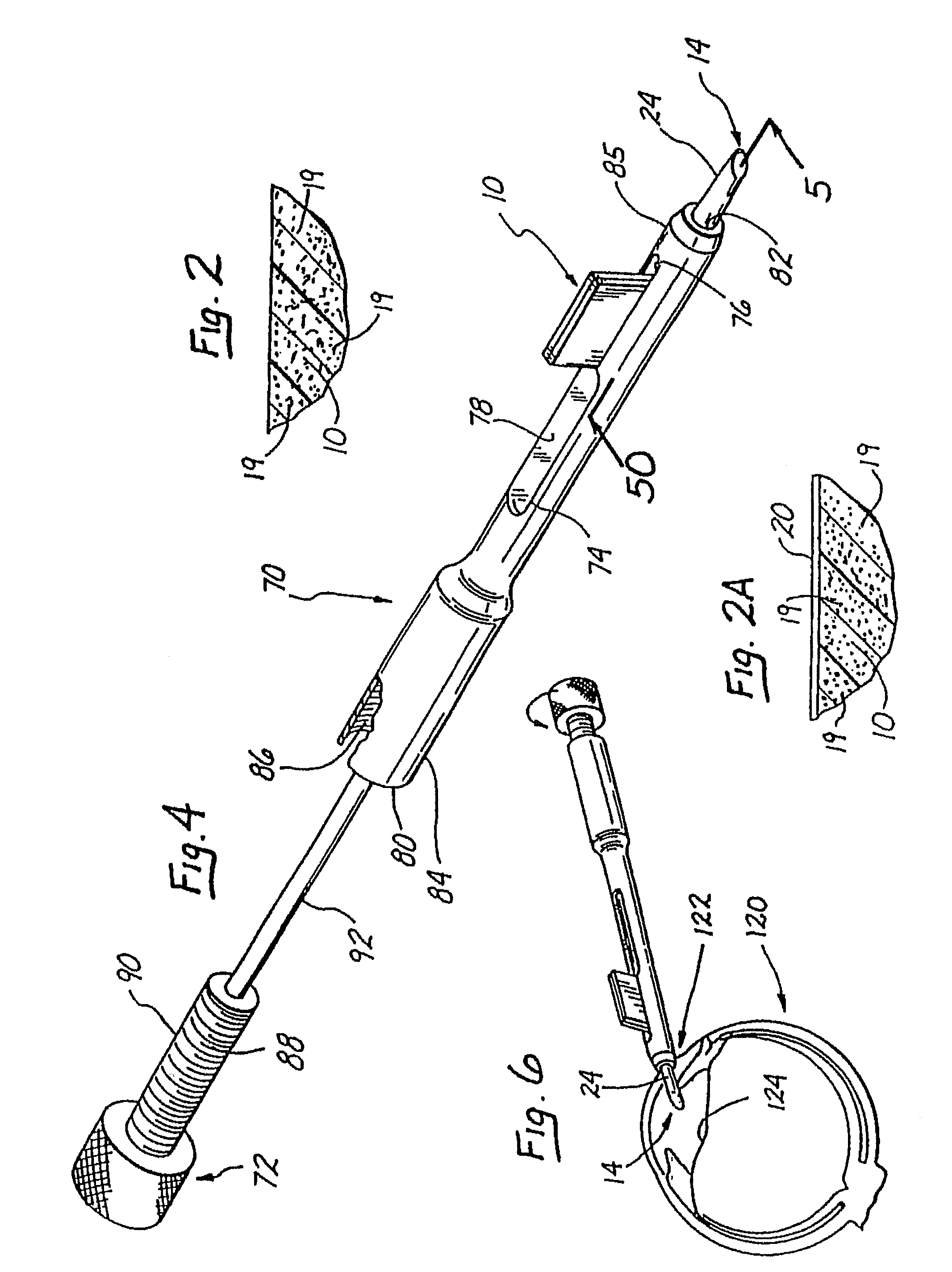
[0068]A series of IOL inserters, similar in configuration to inserter 10, were provided and tested.

[0069]These inserters were as follows:[0070]INSERTER A: molded from polypropylene including 0.25% by weight of glycerol monostearate distributed substantially uniformly throughout. Inserter A was subjected to no plasma processing and no blooming processing.[0071]INSERTER B: molded from polypropylene including 0.25% by weight of glycerol monostearate distributed substantially uniformly throughout. Inserter B was subjected to plasma processing, but no blooming processing.[0072]INSERTER C: molded from polypropylene including 0.25% by weight of glycerol monostearate distributed uniformly throughout. Inserter C was subjected to no plasma processing and to four (4) days of blooming processing.[0073]INSERTER D: molded from polypropylene including 0.25% by weight of glycerol monostearate distributed uniformly throughout. Inserter D was subjected to plasma processing and one (1) day of blooming...


PUM


Abstract

Apparatus for inserting intraocular lenses (IOLs) into eyes include a hollow tube including a material and having an interior wall defining a hollow space through which an IOL is passed and an outlet through which the IOL is passed from the hollow space into an eye, and a lubricity enhancing component physically secured to said hollow tube and concentrated at or near the interior wall in an amount effective to facilitate the passage of the IOL through the hollow space.

Description

RELATED APPLICATIONS[0001]The application is a division of application Ser. No. 10 / 077,615, filed Feb. 15, 2002, now U.S. Pat. No. 6,679,891 which is a division of application Ser. No. 09 / 535,267, filed Mar. 23, 2000, now U.S. Pat. No. 6,398,788, issued Jun. 4, 2002, which is a division of application Ser. No. 09 / 236,541, filed Jan. 25, 1999, now U.S. Pat. No. 6,083,230, issued Jul. 4, 2000, which is a division of application Ser. No. 08 / 903,282, filed Jul. 30, 1997, now U.S. Pat. No. 5,942,277, issued Aug. 24, 1999, which is a division of parent application Ser. No. 08 / 676,699, filed Jul. 10, 1996, now U.S. Pat. No. 5,716,364, issued Feb. 10, 1998.BACKGROUND OF THE INVENTION[0002]The present invention relates to apparatus for inserting an intraocular lens through a small incision into an eye, to methods for making such apparatus and to methods for inserting an intraocular lens into an eye. More particularly, the invention relates to an apparatus which has enhanced lubricity and is ...

Claims


Application Information

Patent Timeline
Patent Type & Authority Patents(United States)
IPC IPC(8): B05D7/22A61F2/16A61F9/00
CPCA61F2/1664A61F2/1675
Inventor MAKKER, HARISHYANG, SHIH-LIANG S.BRADY, DANIEL G.GLICK, ROBERT E.
Owner JOHNSON & JOHNSON SURGICAL VISION INC
Why Eureka
Try Eureka