Crystal oscillator

a crystal oscillator and oscillator technology, applied in the field of crystal oscillators, can solve the problems of inability to use the crystal oscillator in general use, the cost of conventional crystal oscillators remains high, and the usable range of crystal oscillators becomes extremely limited, so as to achieve the effect of improving the value of the crystal oscillator

Active Publication Date: 2008-03-25
SEIKO EPSON CORP
View PDF2 Cites 6 Cited by
  • Summary
  • Abstract
  • Description
  • Claims
  • Application Information

AI Technical Summary

Benefits of technology

[0013]An advantage of the invention is to provide a crystal oscillator that can change the waveform output of the oscillation signal depending on the purpose of use.
[0014]According to an aspect of the invention, a crystal oscillator that outputs an oscillation output signal of an oscillator circuit oscillated by a crystal resonator as a resonation source via a buffer circuit, includes: a plurality of waveform output circuits provided in the buffer circuit, each converting, when inputted, the oscillation output signal into a different waveform and outputting the converted signal; a circuit selection switch that selects any one of the plurality of waveform output circuits as a waveform output circuit of the buffer circuit; and a memory circuit that stores data used by the circuit selection switch to select any one of the waveform output circuits.
[0015]It is preferable that, with the crystal oscillator of the aspect of the invention, the oscillator circuit includes a voltage control oscillator circuit having a voltage variable capacitance element and a temperature-compensating voltage generator circuit that performs temperature compensation using the voltage variable capacitance element, and that the memory circuit stores temperature compensation data used to compensate the temperature characteristics of the crystal resonator.
[0016]It is preferable that the crystal oscillator of the aspect of the invention is composed at least of the oscillator circuit, the buffer circuit, the circuit selection switch, and the memory circuit loaded on one chip.
[0017]According to the aspect of the invention, the buffer circuit is equipped with: the plurality of waveform output circuits provided in the buffer circuit, each converting, when inputted, the oscillation output signal into a different waveform and outputting the converted signal; the circuit selection switch that selects any one of the plurality of waveform output circuits as the waveform output circuit of the buffer circuit; and the memory circuit that stores data used by the circuit selection switch to select any one of the waveform output circuits. It thus becomes possible to change the waveform output of the oscillation signal that is outputted from the waveform output circuit in accordance with the purpose of use of the crystal oscillator.
[0018]As a consequence, a single crystal oscillator may perform as the crystal oscillator that serves a plurality of purposes, and the value of the crystal oscillator may improve.

Problems solved by technology

In this case, however, the crystal oscillator 100 becomes a unit only for a use that requires the sine wave output, and the usable range as a crystal oscillator becomes extremely limited.
In other words, with the conventional crystal oscillator, if the demand on its performance differs depending on the purpose of use, it is necessary to produce crystal oscillators equipped with waveform output circuits to satisfy different demands, and, thus, the conventional crystal oscillators stay costly and have not been put in general use.

Method used


Image

  • Crystal oscillator
  • Crystal oscillator
  • Crystal oscillator

Examples


Embodiment Construction

[0031]An embodiment of the invention will now be described. In the present embodiment, a temperature-compensated crystal oscillator (TCXO) is described as one example of the crystal oscillator of the embodiment of the invention.

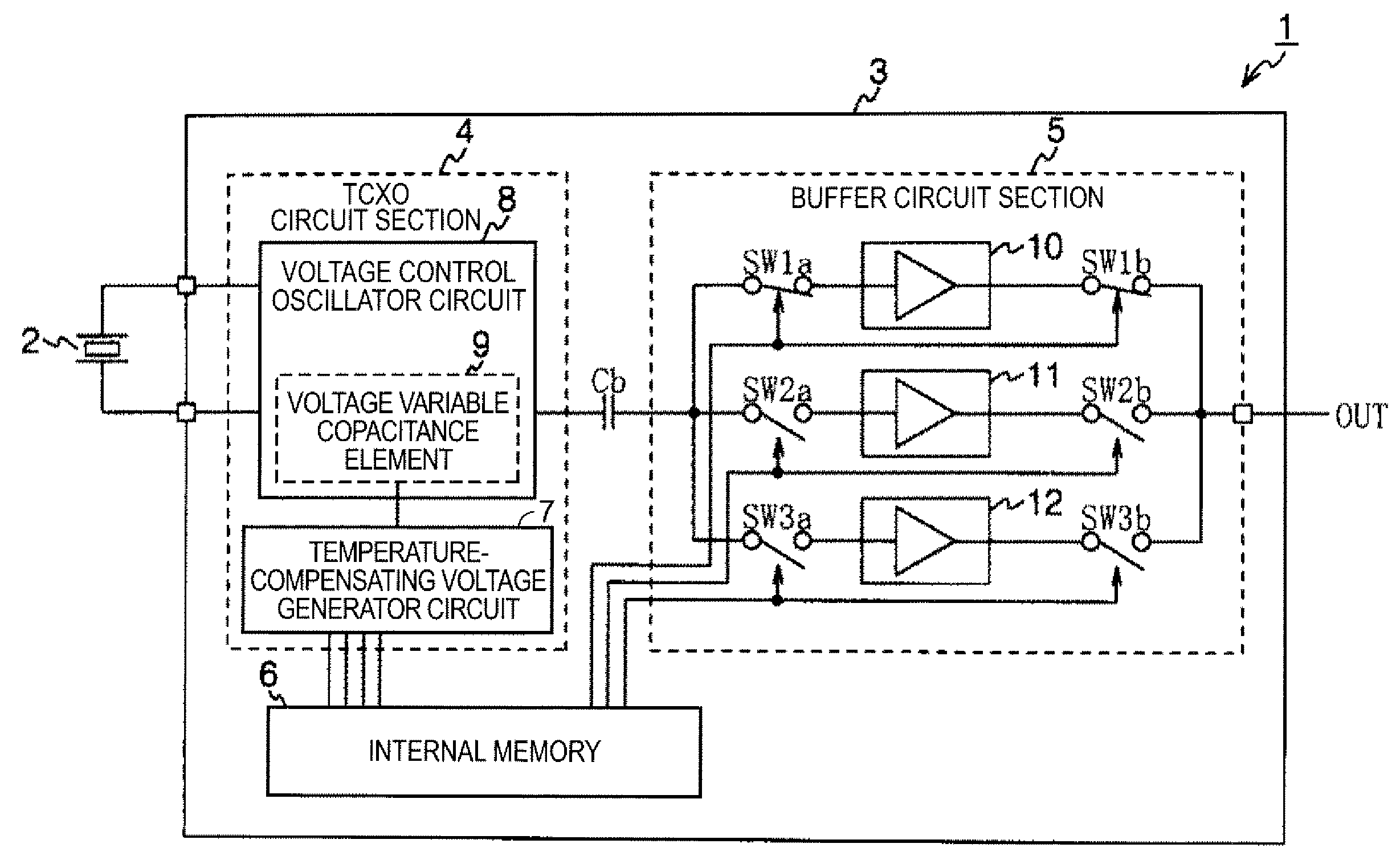
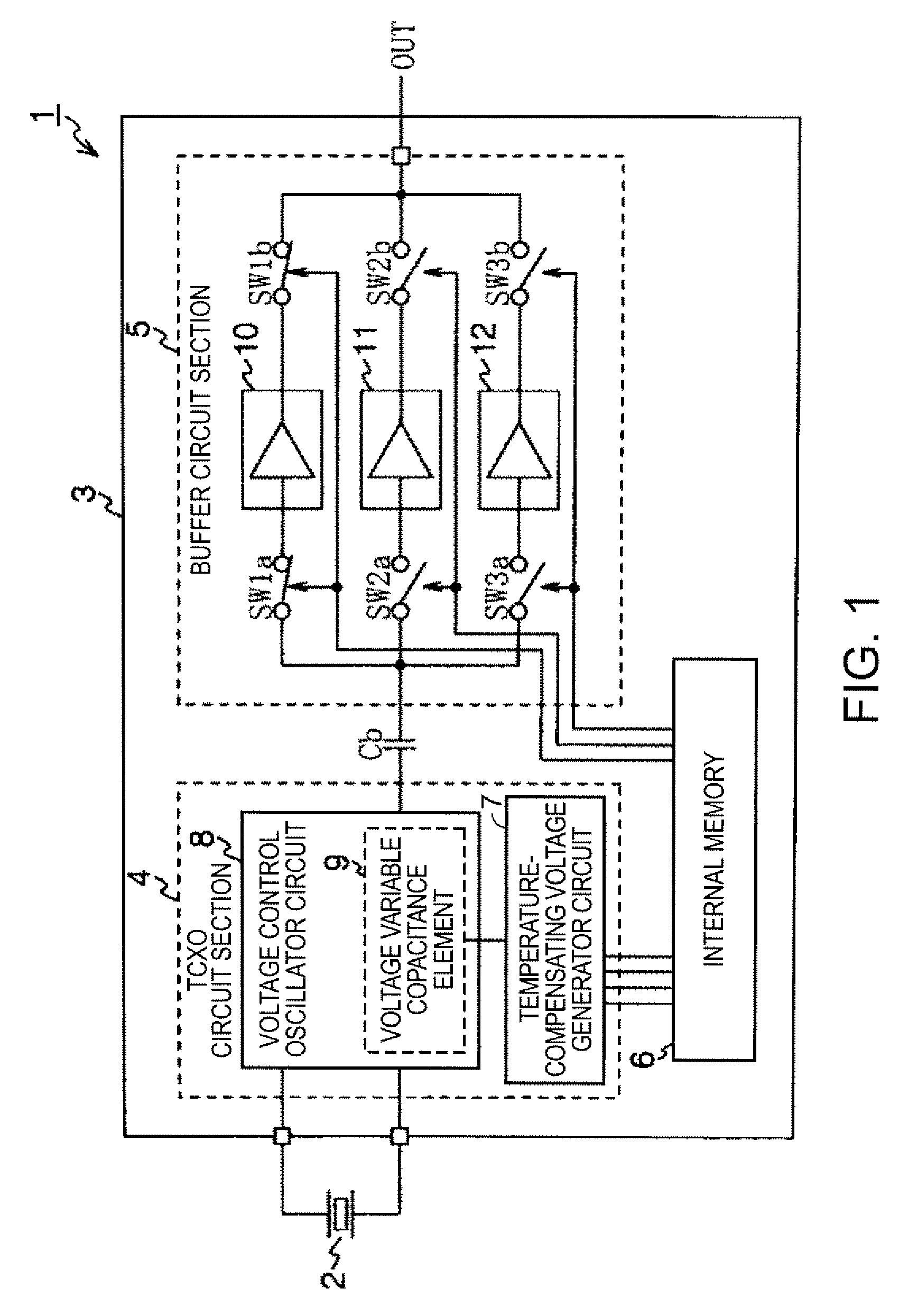
[0032]FIG. 1 is a schematic diagram showing the composition of the TCXO of the embodiment of the invention.

[0033]A TCXO 1 shown in FIG. 1 is composed of a crystal resonator 2 and a single-chip IC 3. On the single-chip IC 3, a TCXO circuit section 4 excluding the crystal resonator 2, a buffer circuit section 5, and an internal memory circuit 6 are integrated. The TCXO circuit section 4 is equipped with a temperature-compensating voltage generator circuit 7, a voltage variable capacitance element 9, and a voltage control oscillator circuit 8 capable of oscillation frequency control by the voltage.

[0034]The internal memory circuit 6 stores setting parameters of the temperature-compensating voltage generator circuit 7 that outputs a temperature-compensating volta...


PUM


Abstract

A crystal oscillator that outputs an oscillation output signal of an oscillator circuit oscillated by a crystal resonator as a resonation source via a buffer circuit, includes: a plurality of waveform output circuits provided in the buffer circuit, each converting, when inputted, the oscillation output signal into a different waveform and outputting the converted signal; a circuit selection switch that selects any one of the plurality of waveform output circuits as a waveform output circuit of the buffer circuit; and a memory circuit that stores data used by the circuit selection switch to select any one of the waveform output circuits.

Description

BACKGROUND[0001]1. Technical Field[0002]The present invention relates to a crystal oscillator particularly suitable as a crystal oscillator having circuits other than a crystal resonator integrated on one chip.[0003]2. Related Art[0004]Conventionally, a temperature-compensated crystal oscillator (TCXO) is widely used in mobile communications apparatuses such as cellular phones.[0005]FIG. 10 is a schematic diagram showing the composition of a conventional temperature-compensated crystal oscillator.[0006]A TCXO 100 shown in FIG. 10 is composed of a crystal resonator 101 and a single-chip IC 102. A TCXO circuit section 103 excluding the crystal resonator 101 and an internal memory circuit 104 are integrated on the single-chip IC 102. The TCXO circuit section 103 is composed of a temperature-compensating voltage generator circuit 105 and a voltage control oscillator circuit 106. The temperature-compensating voltage generator circuit 105 generates a temperature-compensating voltage based...

Claims


Application Information

Patent Timeline
Patent Type & Authority Patents(United States)
IPC IPC(8): H03B5/32
CPCH03B5/36
Inventor YAMAMOTO, TAKEHIRO
Owner SEIKO EPSON CORP
Why Eureka
Try Eureka