System and method for hinge memory mitigation

a technology of hinge memory and mitigation system, applied in the field of display system, can solve the problems of micromirror b> failure, micromirror b> failure, degradation of phosphor screen in cathode ray tube, etc., and achieve the effect of reducing failures

a technology of hinge memory and mitigation system, applied in the field of display system, can solve the problems of micromirror b> failure, micromirror b> failure, degradation of phosphor screen in cathode ray tube, etc., and achieve the effect of reducing failures

US7349146B1Active Publication Date: 2008-03-25TEXAS INSTR INC

Image

  • System and method for hinge memory mitigation
  • System and method for hinge memory mitigation
  • System and method for hinge memory mitigation

Examples


Embodiment Construction

[0025]The making and using of the presently preferred embodiments are discussed in detail below. It should be appreciated, however, that the present invention provides many applicable inventive concepts that can be embodied in a wide variety of specific contexts. The specific embodiments discussed are merely illustrative of specific ways to make and use the invention, and do not limit the scope of the invention.

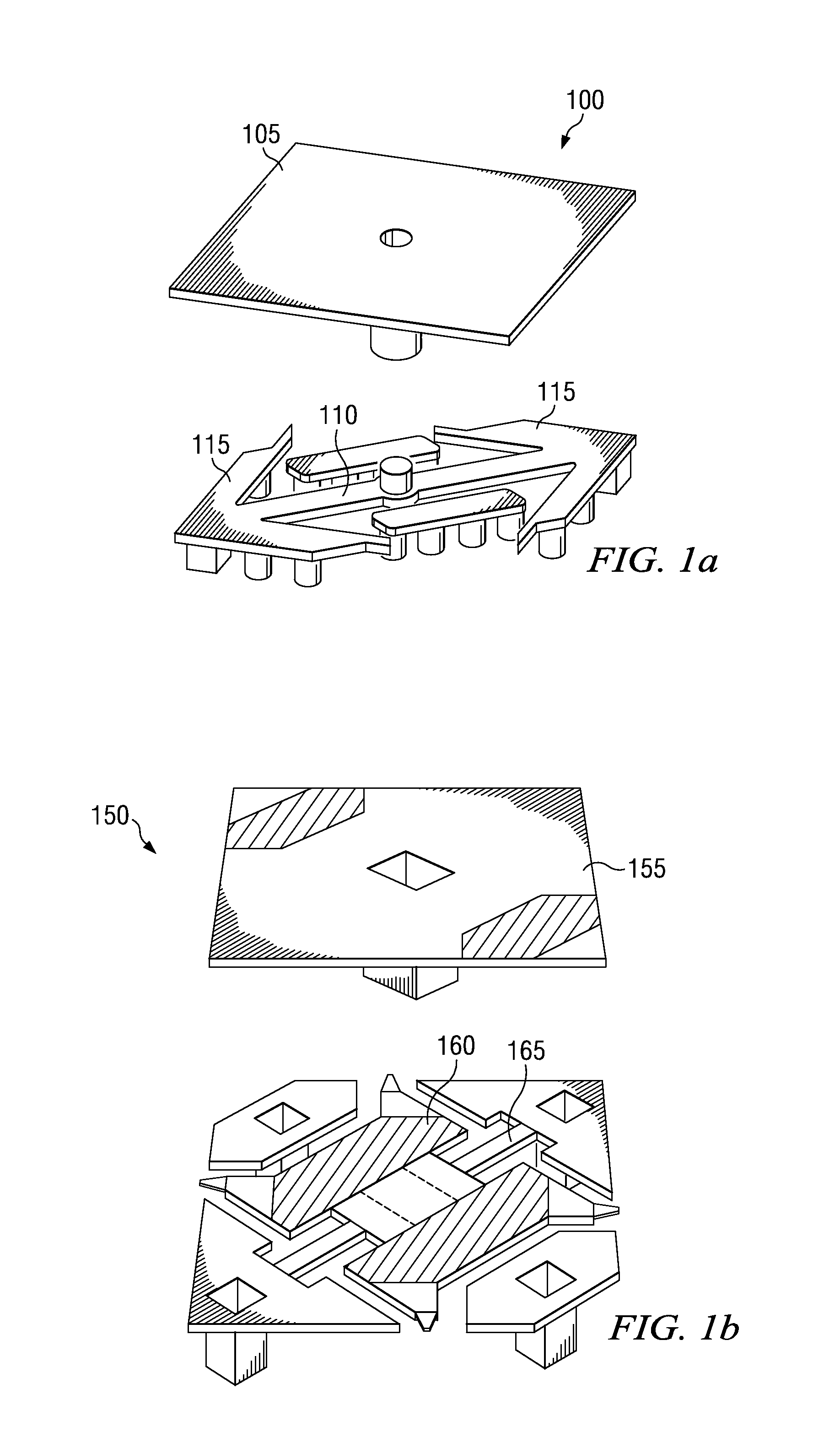
[0026]The present invention will be described with respect to preferred embodiments in a specific context, namely a microdisplay display system utilizing a digital micromirror device. The invention may also be applied, however, to other micro electrical mechanical systems (MEMS) that can perform repetitive operations. Additionally, the present invention can be applied to other types of display systems, such as plasma display systems, wherein pixel usage can be tracked and the usage information can be used to help reduce the effects of pixel burn-in, for example.
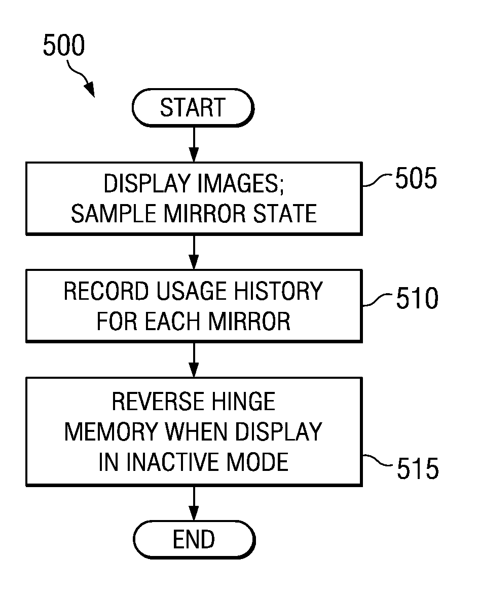
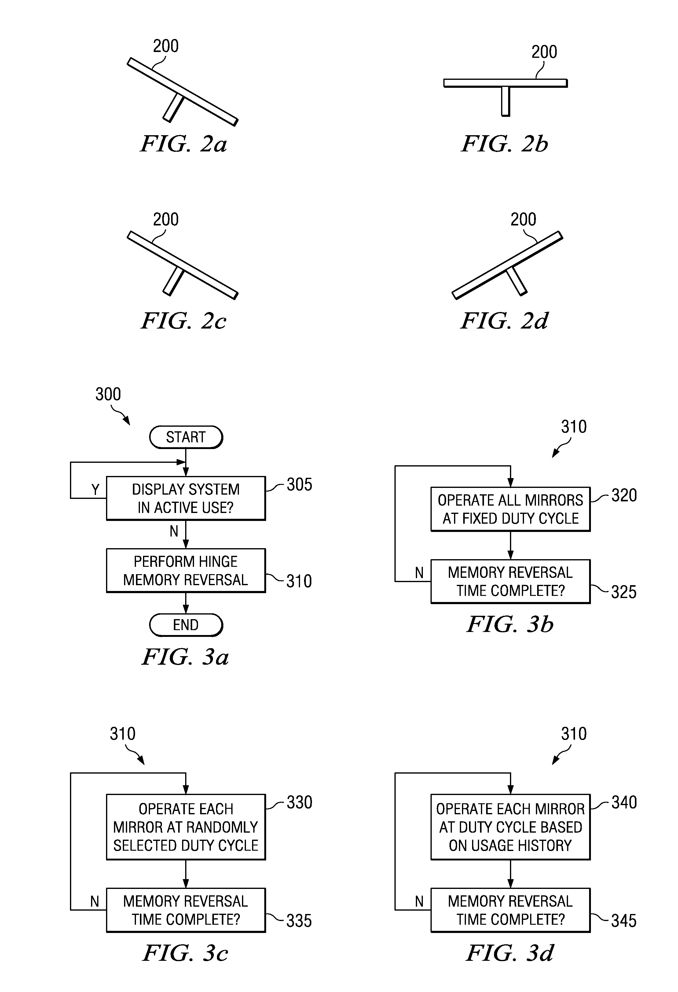
[0027]Hinge me...


PUM


Abstract

System and method for reducing failures due to hinge memory in a microdisplay display system. A preferred embodiment includes setting the state of each micromirror in a digital micromirror device based on an image being displayed, recording a usage history for the micromirrors, and providing a sequence of states to each micromirror when the display system is in an inactive mode. The sequence of states provided to a micromirror is based on the micromirror's usage history. The operation of the micromirrors while a display system containing the digital micromirror device is not in active use can help to reverse or eliminate hinge memory, thereby extending the lifetime of the digital micromirror device.

Description

TECHNICAL FIELD[0001]The present invention relates generally to a system and method for display systems, and more particularly to a system and method for reducing failures due to hinge memory in a microdisplay display system.BACKGROUND[0002]A microdisplay display system utilizes an array of spatial light modulators (the microdisplay) to modulate light in order to display images on a display plane. The microdisplay can modulate light by reflectively altering the transmission path of the light or blocking the transmission path of the light. Microdisplay display systems have enabled the production of high quality display systems at a reasonable cost.[0003]One widely used form of microdisplay is a digital micromirror device (DMD). A DMD is made up of an array of hundreds of thousands of micromirrors that pivot along a common axis depending upon an image being displayed. A single image can be divided into a number of bit planes, which when displayed sequentially, are integrated by the hu...

Claims


Application Information

Patent Timeline
25 Mar 2008
Publication
US7349146B1
IPC
G02B26/00; G02B26/08; G09G3/34; G06K7/10
CPC
G02B26/0833
Inventors
DOUGLASS, MICHAEL RICHARD; SONTHEIMER, ANDREW B.