High-heat-dissipation lighting module

a lighting module and high heat dissipation technology, applied in lighting and heating equipment, semiconductor devices for light sources, instruments, etc., can solve the problems of effectively cooling leds, difficult production, and further compounding of the problem of difficult to produce, and achieve the effect of high heat dissipation capacity, cheap and easy production

Inactive Publication Date: 2008-03-25
FRAEN CORPORATION
View PDF14 Cites 85 Cited by
  • Summary
  • Abstract
  • Description
  • Claims
  • Application Information

AI Technical Summary

Benefits of technology

[0006]It is an object of the present invention to provide a lighting module of the type incorporating a solid-state light source (LED) and a lens, designed to provide a solution to the aforementioned problems of the known state of the art. More specifically, it is an object of the invention to provide a module with a high heat dissipation capacity, and which at the same time is cheap and easy to produce.

Problems solved by technology

By housing the LED / lens assembly inside a casing, this and other similar modules (a further example is described in U.S. Pat. No. 6,274,924) are difficult to produce, mainly on account of the necessity to assemble and connect the various component parts (the lens, in particular, is normally glued), and also have the major drawback of failing, in use, to effectively disperse the heat generated by the LED.
The problem of effectively cooling the LED is further compounded when the LED is housed inside a recess in the lens, in which case, dissipating plates fitted to the LED mount may not always be sufficient.
A further drawback lies in the lens normally being molded in a one-piece body from transparent polymer material.
And since the lens is relatively thick, with an axial dimension comparable (i.e. substantially equal to or greater than) the transverse dimension, a relatively long molding time is required.
Moreover, the efficiency of total-internal-reflection lenses (and, therefore, of lighting modules equipped with them) is greatly affected by the condition of the reflecting surface, and may be impaired in the event the surface is damaged or even only contaminated.
The problem therefore arises of effectively protecting the reflecting surface, both in use and, above all, when manufacturing and handling the lens and assembling the lighting module.

Method used


Image

  • High-heat-dissipation lighting module
  • High-heat-dissipation lighting module
  • High-heat-dissipation lighting module

Examples


Embodiment Construction

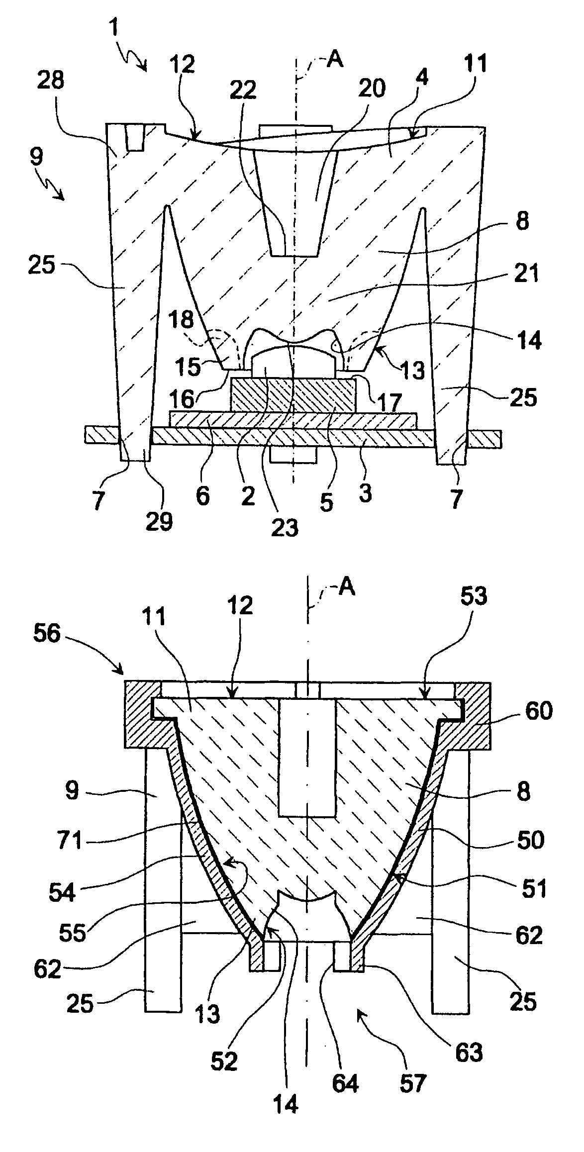
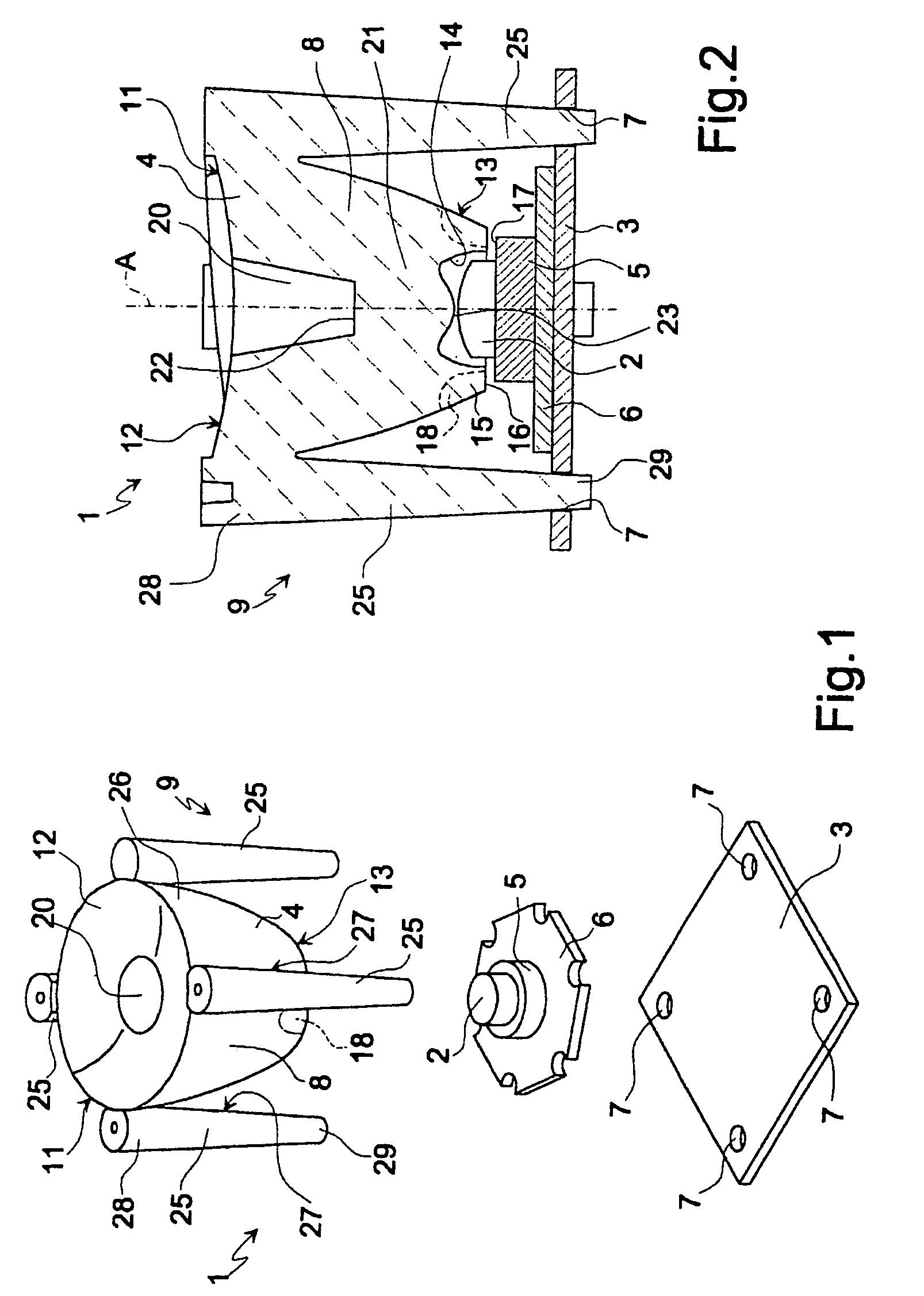
[0016]Number 1 in FIGS. 1 and 2 indicates a lighting module comprising a solid-state light source 2, in particular a LED, a supporting plate 3, and a lens 4.

[0017]LED 2 is supported on a known mount 5 (shown only schematically) comprising an optional known dissipating plate 6. For the sake of simplicity, known contacts and connections for connecting LED 2 electrically to an external network are not shown. Mount 5 (or dissipating plate 6, if any) is fixed to plate 3 by known heat-conducting adhesive.

[0018]Plate 3 is a substantially flat heat-dissipating plate of any shape made, for example, of metal material, and has four seats 7 defined by respective circular-section through holes.

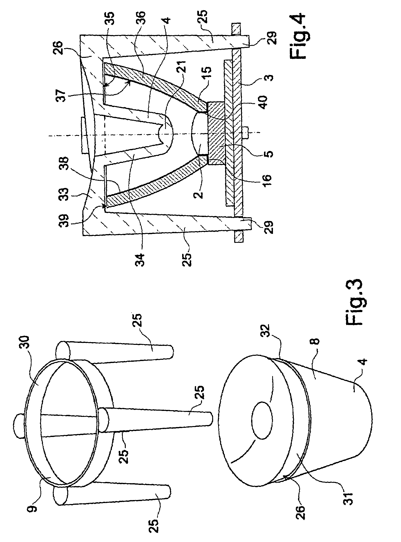
[0019]Lens 4 is a total-internal-reflection lens, and comprises a substantially cup-shaped optical body 8 made of transparent plastic material (e.g. polycarbonate PC or polymethyl methacrylate PMMA); and a supporting structure 9 by which lens 4 is supported by and projects from plate 3.

[0020]In the example...


PUM


Abstract

There is provided a lighting module of the type having a solid-state light source, in particular a LED, a supporting plate, and a lens; the lens has a recess housing the light source; the lens is supported by and projects from the plate by means of supporting members (25) carried by the lens and for fitting the lens directly to the plate; and the supporting members are formed in one piece with the lens, and are spaced apart and separated from one another by cooling windows.

Description

TECHNICAL FIELD[0001]The present invention relates to a high-heat-dissipation lighting module of the type comprising a solid-state light source, in particular a LED, connected to a lens.BACKGROUND ART[0002]A lighting module of this type is known, for example, from Japanese Patent Application JP 61-147585, which describes a module comprising a LED supported on a mount, and a total-internal-reflection lens having a recess in which the LED is housed; and both the lens and the LED are housed in a cylindrical casing. By housing the LED / lens assembly inside a casing, this and other similar modules (a further example is described in U.S. Pat. No. 6,274,924) are difficult to produce, mainly on account of the necessity to assemble and connect the various component parts (the lens, in particular, is normally glued), and also have the major drawback of failing, in use, to effectively disperse the heat generated by the LED.[0003]The problem of effectively cooling the LED is further compounded w...

Claims


Application Information

Patent Timeline
Patent Type & Authority Patents(United States)
IPC IPC(8): G02B13/18F21V5/00F21V7/00G02B17/00G02B3/08G02B7/02F21K99/00F21V3/04F21V5/04F21V29/00H01L33/58H01L33/60
CPCF21K9/00F21V3/04F21V5/04F21V7/0091F21V29/004F21V29/2212F21V17/005G02B7/028G02B17/00F21V17/101H01L33/58H01L33/60F21Y2101/02F21Y2115/10F21K9/69F21K9/68F21V29/76
Inventor ANGELINI, MARCOBIGLIATI, CLAUDIABARALDO, NATALESCODES, LUCA
Owner FRAEN CORPORATION
Why Eureka
Try Eureka