Optical disk apparatus having variable reproduction speed function

Inactive Publication Date: 2008-03-25
TEAC CORP
View PDF12 Cites 0 Cited by
  • Summary
  • Abstract
  • Description
  • Claims
  • Application Information

AI Technical Summary

Benefits of technology

[0008]The present invention provides an optical disk apparatus which enables a user to readily and reliably adjust the data

Problems solved by technology

The sound data are not output from a sound output terminal of the optical d

Method used


Image

  • Optical disk apparatus having variable reproduction speed function
  • Optical disk apparatus having variable reproduction speed function
  • Optical disk apparatus having variable reproduction speed function

Examples


Embodiment Construction

[0023]An embodiment of the present invention will be described hereinbelow by reference to the drawings.

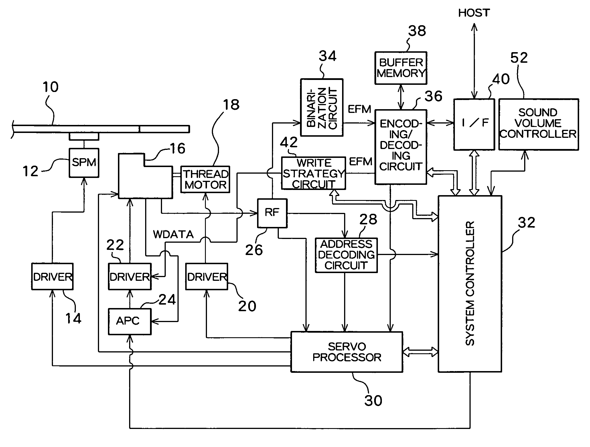
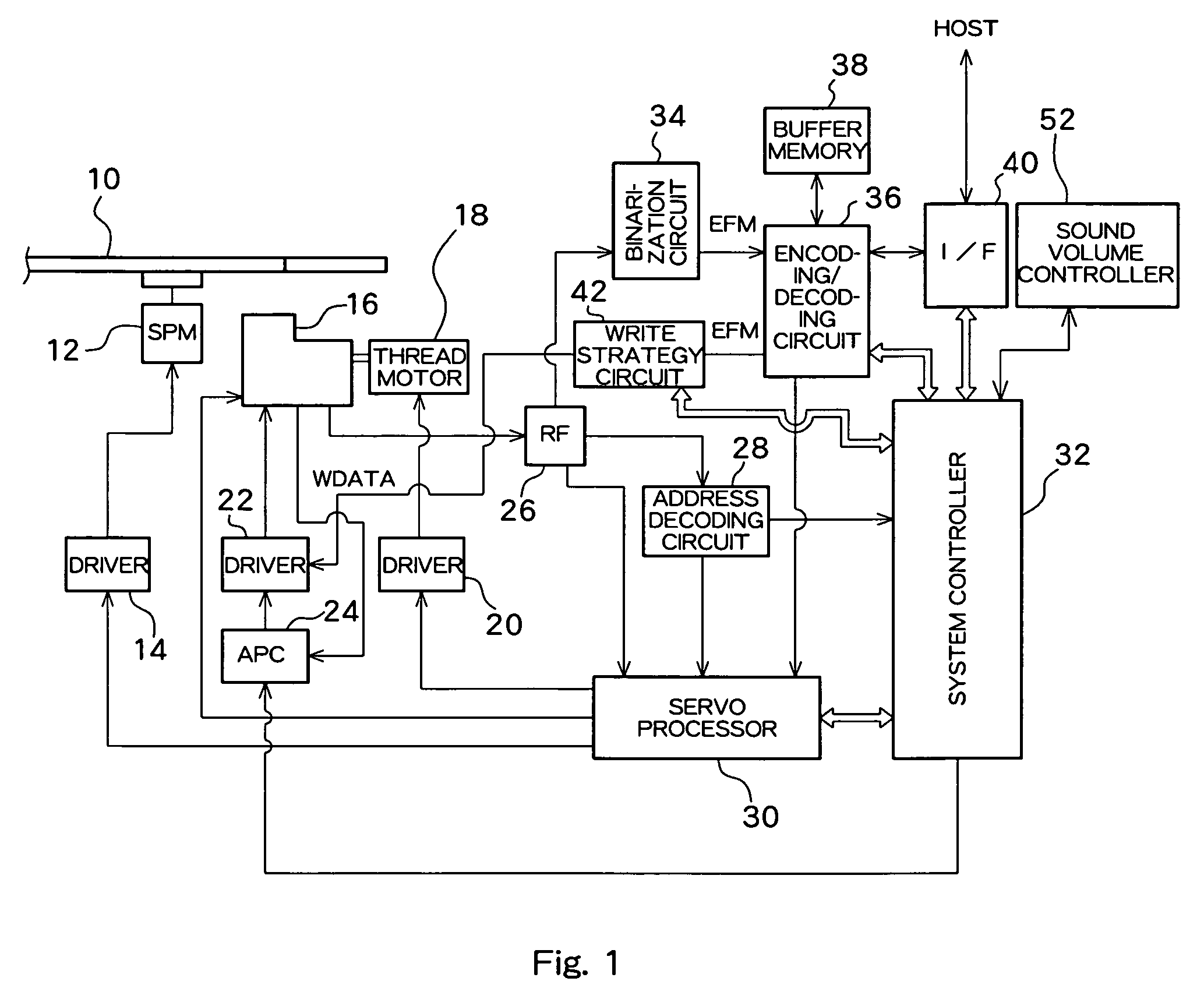
[0024]FIG. 1 shows a block diagram of the entirety of an optical disk apparatus according to the embodiment. An optical disk 10, such as a CD or a DVD, is rotationally driven by a spindle motor (SPM) 12. The spindle motor SPM 12 is driven by a driver 14, and the driver 14 is servo-controlled by a servo processor 30 so as to yield a desired rotational speed.

[0025]An optical pickup 16 includes a laser diode (LD) for radiating a laser beam on the optical disk 10, and a photo-detector (PD) which receives light reflected from the optical disk 10 and converts the thus-received light into an electrical signal. The optical pickup 16 is disposed opposite the optical disk 10. The optical pickup 16 is driven in a radial direction of the optical disk 10 by a thread motor 18, and the thread motor 18 is driven by a driver 20. The driver 20 is servo-controlled by the servo processor 30 in the sa...


PUM


Abstract

An optical disk apparatus which varies a rotational speed of an optical disk through use of a sound volume controller. A controller of the optical disk apparatus causes a sound volume controller to act as a rotational speed controller upon receipt of a READ command from a host apparatus. The controller detects a set position of the sound volume controller on the basis of a signal output from the same and controls a spindle motor in accordance with a detected position, thereby changing a rotational speed of said optical disk. When wind sound or the like, of the optical disk is obtrusive for the user, the user can diminish noise by means of decreasing the rotational speed through actuation of the sound volume controller.

Description

BACKGROUND OF THE INVENTION[0001]1. Field of the Invention[0002]The present invention relates to an optical disk apparatus, and more particularly, to a technique for adjusting a speed at which data on an optical disk are to be reproduced.[0003]2. Prior Art[0004]In the field of an optical disk apparatus which records and reproduces data on and from an optical disk, such as a CD or a DVD, a technique for rendering a data reproduction speed not constant but variable has been known. For instance, a prior art reference provided below describes a technique for reducing a rotational speed of a CD when a tray transport operation key is actuated for a short period of time and performing ordinary CD tray transport operation when the tray transport operation key is pressed for a comparatively long period of time.[0005]Japanese Utility-Model Registration No. 3084075[0006]Generally, with a view toward increasing the data reproduction speed, an optical disk apparatus rotationally drives an optica...

Claims


Application Information

Patent Timeline
IPC IPC(8): G11B7/00G11B5/09G11B33/10G11B19/08G11B19/16G11B19/18G11B19/26G11B19/28
CPCG11B19/08G11B19/18G11B19/26
Inventor MIYAMOTO, TAKASHIYAMAGUCHI, TADASHI
Owner TEAC CORP
Why Eureka
Try Eureka