Edge wheel dry manifold

a technology of manifold and edge wheel, which is applied in the direction of cleaning using liquids, drying machines with progressive movements, lighting and heating apparatus, etc. it can solve the problems of unacceptable residues or contaminants entering the processing environment, and achieve the effects of reducing waste, reducing waste, and being easy to manufacture and inexpensively

Inactive Publication Date: 2008-04-01
LAM RES CORP
View PDF33 Cites 10 Cited by
  • Summary
  • Abstract
  • Description
  • Claims
  • Application Information

AI Technical Summary

Benefits of technology

[0016]The advantages of the present invention over the prior art are numerous. One notable benefit and advantage of the invention is the prevention of fluids being re-deposited around the periphery of a substrate during spin drying. Although SRD apparatus are and can be extremely effective for substrate drying and the removal of sources of residue on substrate surfaces, micro-dots of fluids, and corresponding residues, are consistently re-deposited around the periphery of a substrate positioned in edge wheels as the edge wheels accumulate and trap fluids expelled from the surface of a substrate during drying operations. Embodiments of the present invention provide for the removal of fluids which accumulate and are trapped in the groove of an edge wheel. Removal of such fluids removes the source of fluid re-deposit and achieves superior substrate drying.
[0017]Another benefit is that embodiments of the present invention are easily implemented in existing systems and apparatus, as well as systems and apparatus currently being developed. Component parts are easily and inexpensively manufactured, and yield significant return in reduction of waste and precision of manufacture.

Problems solved by technology

If a wet clean is incomplete or ineffective, or if a post-wet clean drying is incomplete or ineffective, then unacceptable residue or contaminants are introduced into the processing environment, potentially comprising the integrity of the devices being fabricated.

Method used


Image

  • Edge wheel dry manifold
  • Edge wheel dry manifold
  • Edge wheel dry manifold

Examples


Embodiment Construction

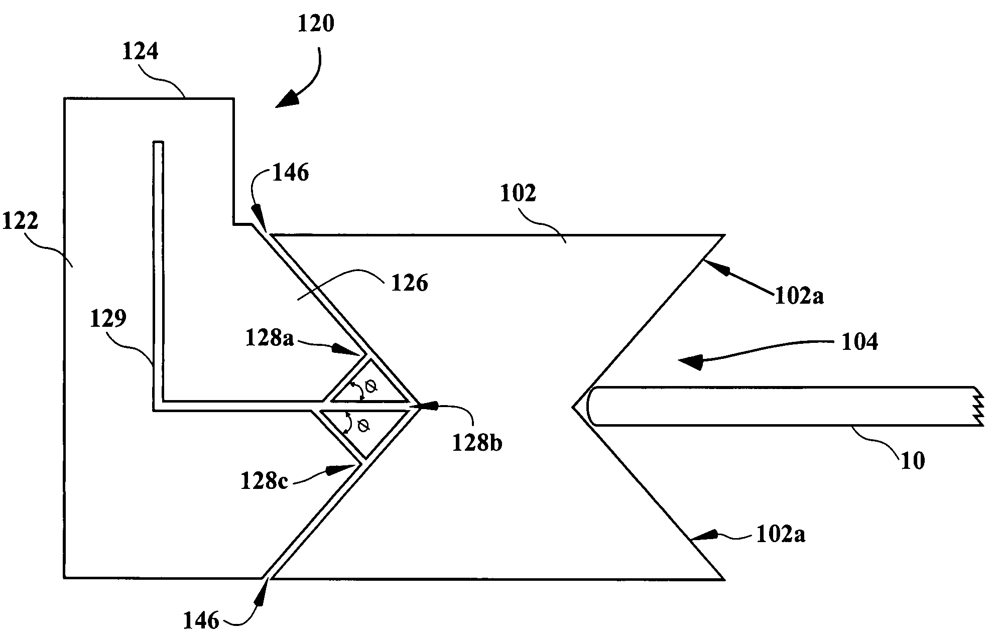
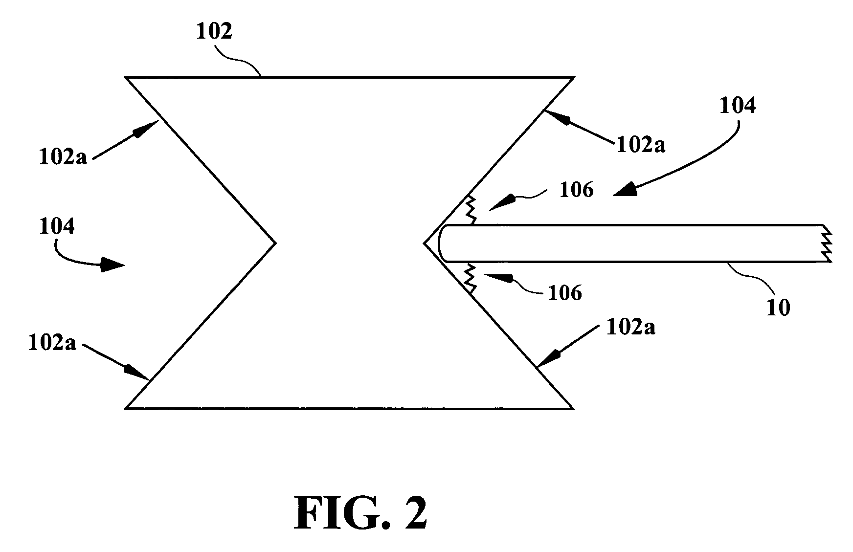
[0030]An invention for substrate processing is described. In preferred embodiments, an edge wheel dry manifold is configured to be defined adjacent to an edge wheel in substrate drying apparatus, and is provided to evacuate fluids from within the edge wheel groove and to prevent the re-depositing of fluids on a peripheral edge of a substrate. In the following description, numerous specific details are set forth in order to provide a thorough understanding of the present invention. It will be understood, however, to one skilled in the art, that the present invention may be practiced without some or all of these specific details. In other instances, well known process operations have not been described in detail in order not to unnecessarily obscure the present invention.

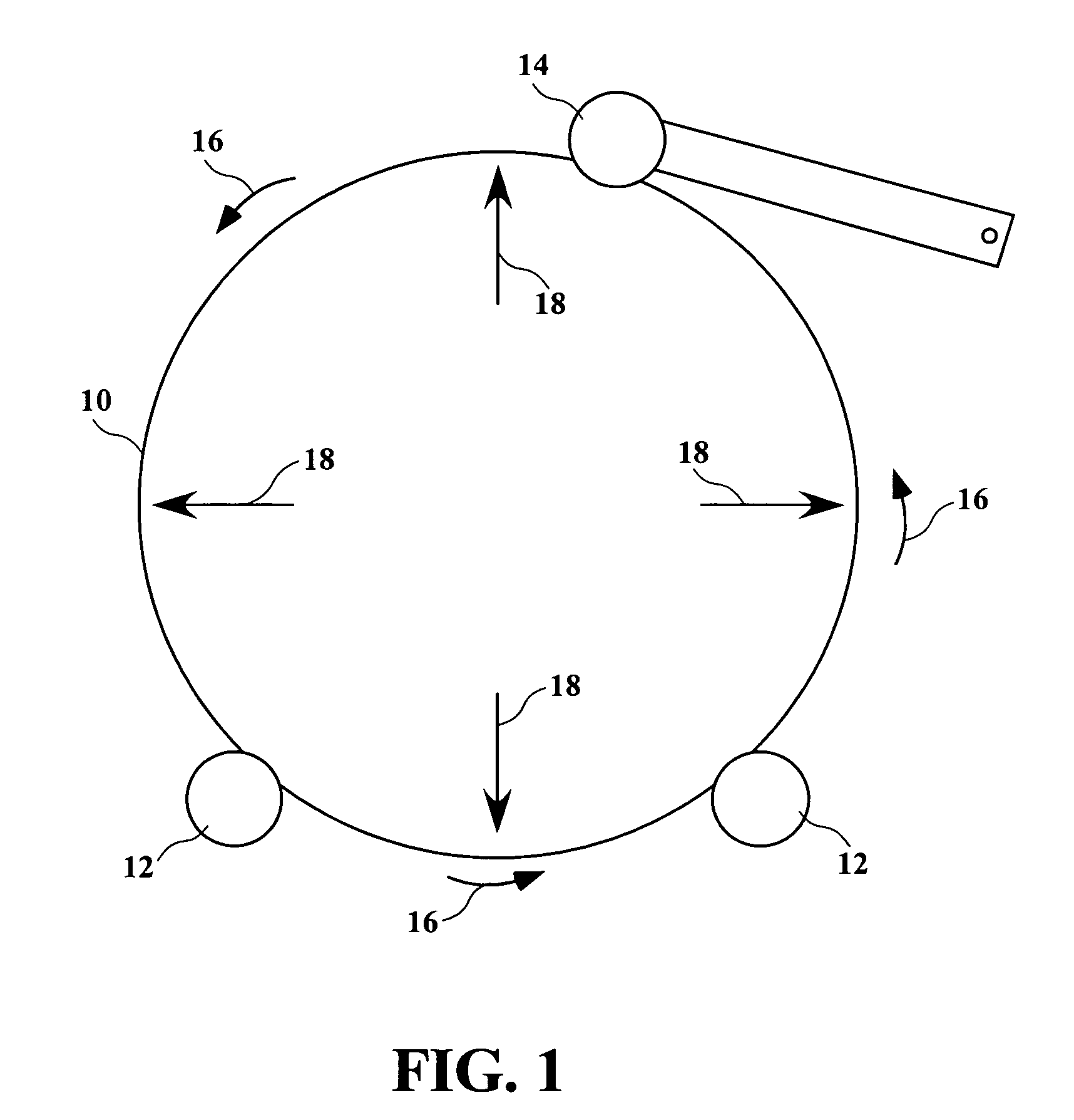
[0031]As is known, one method of drying a substrate is by use of a spin / dry or SRD apparatus, herein after referred to collectively as an SRD apparatus. As described above in reference to FIG. 1, an SRD apparatus uses...


PUM


Abstract

A apparatus for drying a substrate includes a vacuum manifold positioned adjacent to an edge wheel. The edge wheel includes an edge wheel groove for receiving a peripheral edge of a substrate, and the edge wheel is capable of rotating the substrate at a desired set velocity. The vacuum manifold includes a proximity end having one or more vacuum ports defined therein. The proximity end is positioned at least partially within the edge wheel groove, and using supplied vacuum removes fluids that accumulate in the edge wheel groove and prevents re-deposit of trapped fluids around the peripheral edge of the substrate.

Description

BACKGROUND OF THE INVENTION[0001]1. Field of the Invention[0002]The present invention relates generally to substrate cleaning and drying, and more specifically to techniques, systems, and apparatus for preventing fluid deposit and accumulation on substrate surfaces during fabrication processes involving substrates such as a semiconductor wafer, a hard disk, a Liquid Crystal Display (LCD), or a Flat Display Panel (FDP).[0003]2. Description of the Related Art[0004]In a manufacturing processes for fabricating a semiconductor device, an LCD, a magnetic disk, an FDP, etc., there is a need to perform wet cleaning of substrates at various stages of the fabrication process. By way of example, integrated circuit devices are typically manufactured in the form of multi-level structures. At the substrate level, transistor devices having diffusion regions are formed over and into silicon substrates. In subsequent levels, interconnect metallization lines are patterned and electrically connected t...

Claims


Application Information

Patent Timeline
Patent Type & Authority Patents(United States)
IPC IPC(8): F26B13/30B08B5/04H01L21/00H01L21/687
CPCH01L21/67023H01L21/67028H01L21/68707H01L21/6704H01L21/67034H01L21/304H01L21/02
Inventor DAVIS, GLENN W.WOODS, CARLPARKS, JOHNREDEKER, FRED C.RAVKIN, MIKEORBOCK, MICHAEL L.
Owner LAM RES CORP
Why Eureka
Try Eureka