Surgical disk drape and method of dislodging surgical slush within thermal treatment system basins

a technology of thermal treatment system and surgical drapes, which is applied in the field of surgical drapes for use with thermal treatment systems, can solve the problems of compromising sterile conditions, affecting the safety of patients, so as to prevent the placement of conductive items and prevent damage to the sensor

Active Publication Date: 2008-04-01
MICROTEK MEDICAL
View PDF93 Cites 41 Cited by
  • Summary
  • Abstract
  • Description
  • Claims
  • Application Information

AI Technical Summary

Benefits of technology

[0016]Yet another object of the present invention is to insulate a sensor of a thermal treatment system drape from conductive objects placed in a thermal treatment system basin by utilizing a disk for engaging a thermal treatment system dislodgment mechanism to cover and insulate the sensor.
[0019]The positioning of disk member components in the sterile field provides several advantages. Specifically, medical personnel (e.g., a scrub nurse) may manipulate the disk member to connect the drape to the thermal treatment system without compromising sterility of personnel or the sterile field. Further, sensors for surgical drapes (e.g., electrodes to detect leaks as described in one or more of the aforementioned patents and / or patent application publications) may be placed beneath the disk member cover within the drape container to protect the sensor when medical personnel stir the sterile liquid within the thermal treatment system basin. Moreover, this placement may eliminate the need for a protective covering or sleeve for the sensor. The sleeve is typically utilized to prevent damage to the sensor during stirring of the sterile liquid and to inhibit false readings by the sensor when conductive items (e.g., stainless steel pitcher, etc.) are placed in the basin. However, the disk member cover may serve the function of the sleeve within the basin to protect the sensor from damage and to prevent placement of conductive items on the sensor.

Problems solved by technology

Additionally, the glycol or other thermal transfer medium is highly flammable or toxic and, in any event, complicates the procedure.
The Faries, Jr. et al. patent (U.S. Pat. No. 5,163,299) notes that scraping congealed liquid from the drape is undesirable in view of the potential for damage to the drape, resulting in a compromise of sterile conditions.
Although this hand manipulation is somewhat effective, it is not optimal, and often is inconvenient and constitutes an additional chore for operating room personnel.
In addition, when insignificant amounts of liquid are present within a thermal treatment system basin, the system cooling mechanism operates with minimal thermal resistance, thereby enabling the mechanism to become damaged.
Further, the drapes employed by the system may be damaged by being disposed proximate the cooling mechanism without having the liquid to absorb the thermal energy.
Since only sterile drapes are to be used during surgical procedures, a leak in a surgical drape compromises sterility and contaminates the entire surgical procedure, thereby increasing the risk of injury to a patient.
Further, the above-described sensor drapes tend to subject the sensor or electrodes to accidental damage during stirring of solution within the basin by medical personnel.
Moreover, the sensors tend to provide false readings in response to conductive objects placed within the basin in contact with the sensors.
In order to protect the sensor and / or insulate the sensor from objects placed in a basin, a protective sleeve is generally employed, thereby increasing drape materials and costs.

Method used


Image

  • Surgical disk drape and method of dislodging surgical slush within thermal treatment system basins
  • Surgical disk drape and method of dislodging surgical slush within thermal treatment system basins
  • Surgical disk drape and method of dislodging surgical slush within thermal treatment system basins

Examples


Embodiment Construction

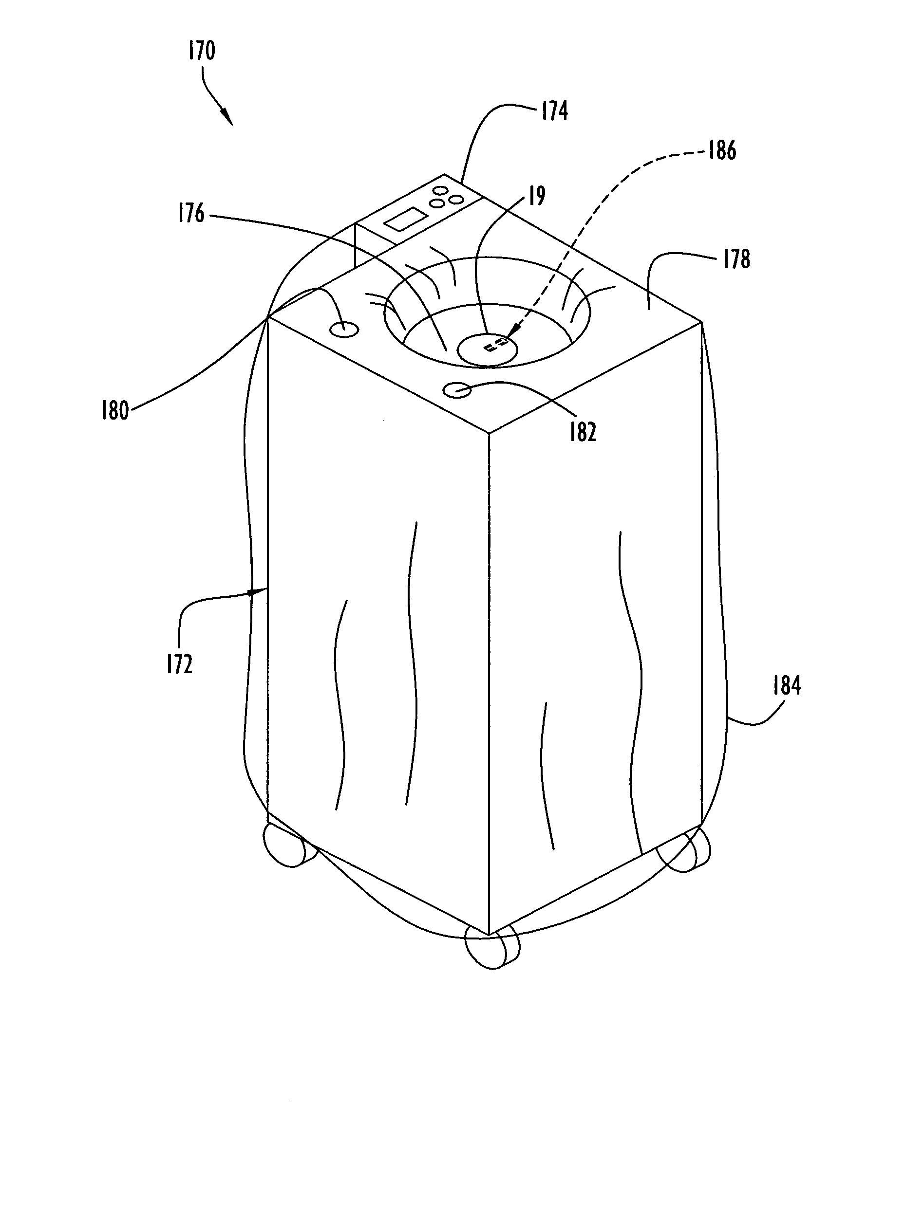
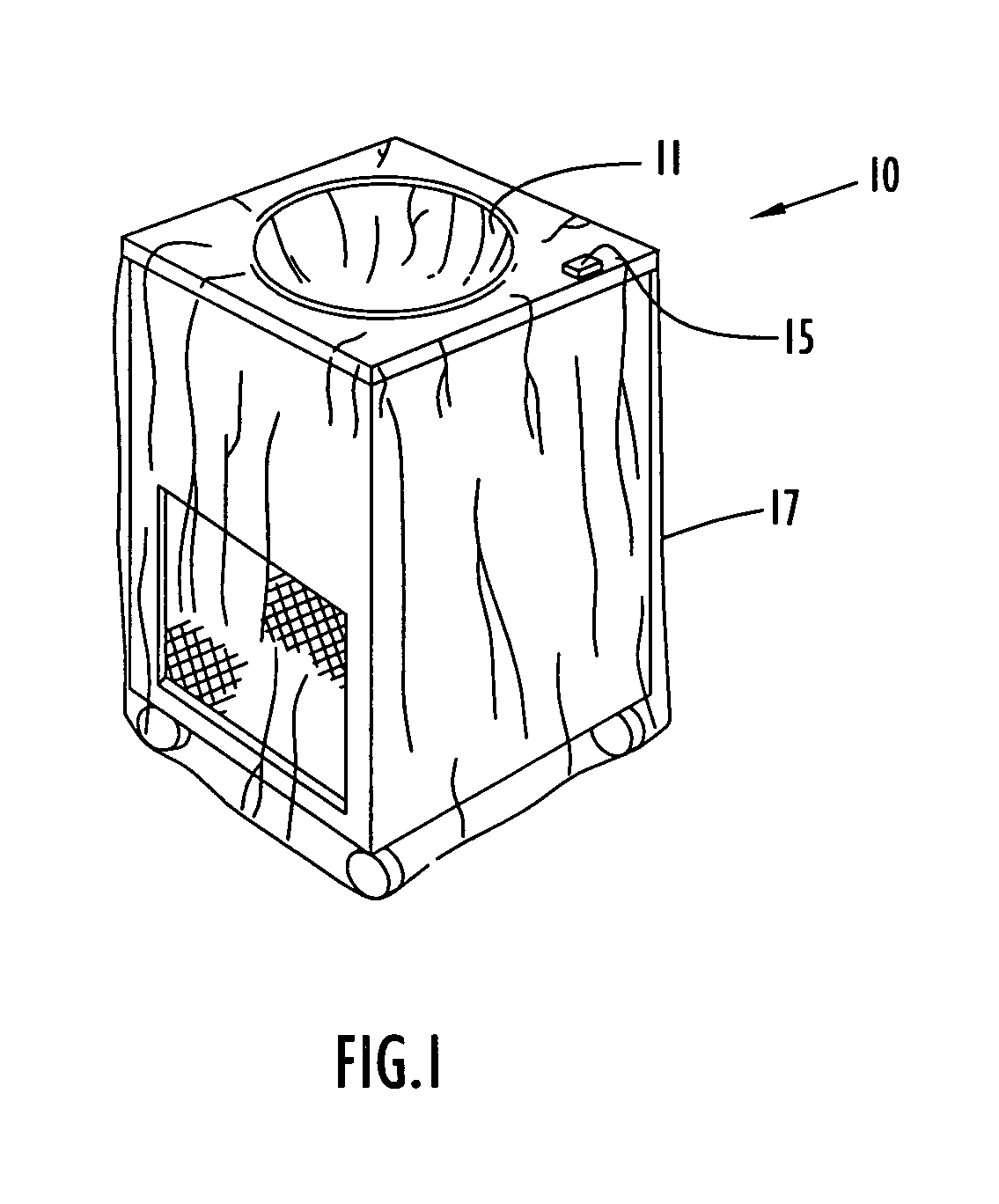
[0028]An exemplary thermal treatment system employing a surgical drape according to the present invention is illustrated in FIG. 1. Specifically, the thermal treatment system is of the type described in one or more of the above-referenced U.S. patents and patent application publications (e.g., U.S. Pat. No. 5,331,820, etc.) and includes a cabinet 10 with a top surface having a basin 11 mounted thereon in an appropriately sized recess. Although shown rounded with a circular rim, basin 11 may be oval, rectangular, square or any desired shape. Basin 11 is made of thermally conductive material, typically stainless steel, and includes a generally flat circular bottom wall and, in the illustrated embodiment, a generally frusto-conical side wall. A conventional refrigeration unit is disposed within cabinet 10 (e.g., it being noted that only an evaporator 13 of that unit is shown in FIG. 4). The refrigeration unit typically includes a compressor, a condenser and an expansion control unit co...


PUM


Abstract

A surgical drape according to the present invention includes a disk member for removable attachment to a thermal treatment system dislodgment mechanism. The mechanism manipulates the drape to dislodge congealed sterile liquid adhered to the sides of a container formed by the drape within a thermal treatment system basin. The disk member includes a base and a cover, where the cover is disposed on the top portion or sterile surface of the drape. The drape sterile surface may further include other disk member components (e.g., base, etc.). In addition, the drape may further include one or more sensors to detect conditions within the drape container.

Description

CROSS-REFERENCE TO RELATED APPLICATIONS[0001]This application claims priority from U.S. Provisional Patent Application Ser. No. 60 / 531,616, entitled “Surgical Disk Drape and Method of Dislodging Surgical Slush Within Thermal Treatment System Basins” and filed Dec. 23, 2003. The disclosure of the above-mentioned provisional application is incorporated herein by reference in its entirety.BACKGROUND OF THE INVENTION[0002]1. Technical Field[0003]The present invention pertains to surgical drapes for use with thermal treatment systems, such as the types of thermal treatment systems disclosed in: U.S. Pat. Nos. 4,393,659 (Keyes et al.), 4,934,152 (Templeton), 5,163,299 (Faries, Jr. et al.), 5,331,820 (Faries, Jr. et al.), 5,333,326 (Faries, Jr. et al.), 5,400,616 (Faries, Jr. et al.), 5,402,644 (Faries, Jr. et al.), 5,429,801 (Faries Jr. et al.), 5,457,962 (Faries, Jr. et al.), 5,502,980 (Faries, Jr. et al.), 5,522,095 (Faries, Jr. et al.), 5,524,643 (Faries, Jr. et al.), 5,551,240 (Faries...

Claims


Application Information

Patent Timeline
Patent Type & Authority Patents(United States)
IPC IPC(8): A61B19/02
CPCA61B19/081A61F7/0085A61B46/10
Inventor FARIES, JR., DURWARD I.HEYMANN, BRUCE R.HENDRIX, DAVID
Owner MICROTEK MEDICAL
Why Eureka
Try Eureka