Self orienting micro plates of thermally conducting material as component in thermal paste or adhesive

a technology of thermally conducting materials and micro plates, which is applied in the direction of non-metal conductors, semiconductor/solid-state device details, conductors, etc., can solve the problems of high power density that cannot be effectively accommodated, high chip operating temperatures, and severe reliability, performance, and lifetime concerns, and achieve the effect of strengthening the platelets against fractur

Active Publication Date: 2008-04-01
GLOBALFOUNDRIES U S INC
View PDF18 Cites 30 Cited by
  • Summary
  • Abstract
  • Description
  • Claims
  • Application Information

AI Technical Summary

Benefits of technology

[0010]Still other aspects and advantages of the present invention will become readily apparent by those skilled in the art from the following detailed description, wherein it is shown and described preferred embodiments of the invention, simply by way of illustration of the best mode contemplated of carrying out the invention. As will be realized the invention is capable of other and different embodiments, and its several details are capable of modifications in various obvious respects, without departing from the invention. Accordingly, the description is to be regarded as illustrative in nature and not as restrictive.

Problems solved by technology

This higher power density can not be effectively accommodated by traditional methods of cooling.
Higher power consumption without concomitant heat removal leads to higher chip operating temperatures which can result in severe reliability, performance, and lifetime concerns. FIG. 1 shows a schematic of a conventional cooling solution comprising a chip mounted on a ceramic module and a heat transfer paste applied to the top surface of the chip and squeezed against a heat sink.
The rate of heat transfer of such cooling designs is limited by the thermal conductivity of the gap filling material.

Method used


Image

  • Self orienting micro plates of thermally conducting material as component in thermal paste or adhesive
  • Self orienting micro plates of thermally conducting material as component in thermal paste or adhesive
  • Self orienting micro plates of thermally conducting material as component in thermal paste or adhesive

Examples


Embodiment Construction

[0024]The term “graphitic” comprehends pure graphite, as well as material that is “substantially graphite,” as well a material having graphite character.

[0025]Reference is made to the figures to illustrate selected embodiments and preferred modes of carrying out the invention. It is to be understood that the invention is not hereby limited to those aspects depicted in the figures.

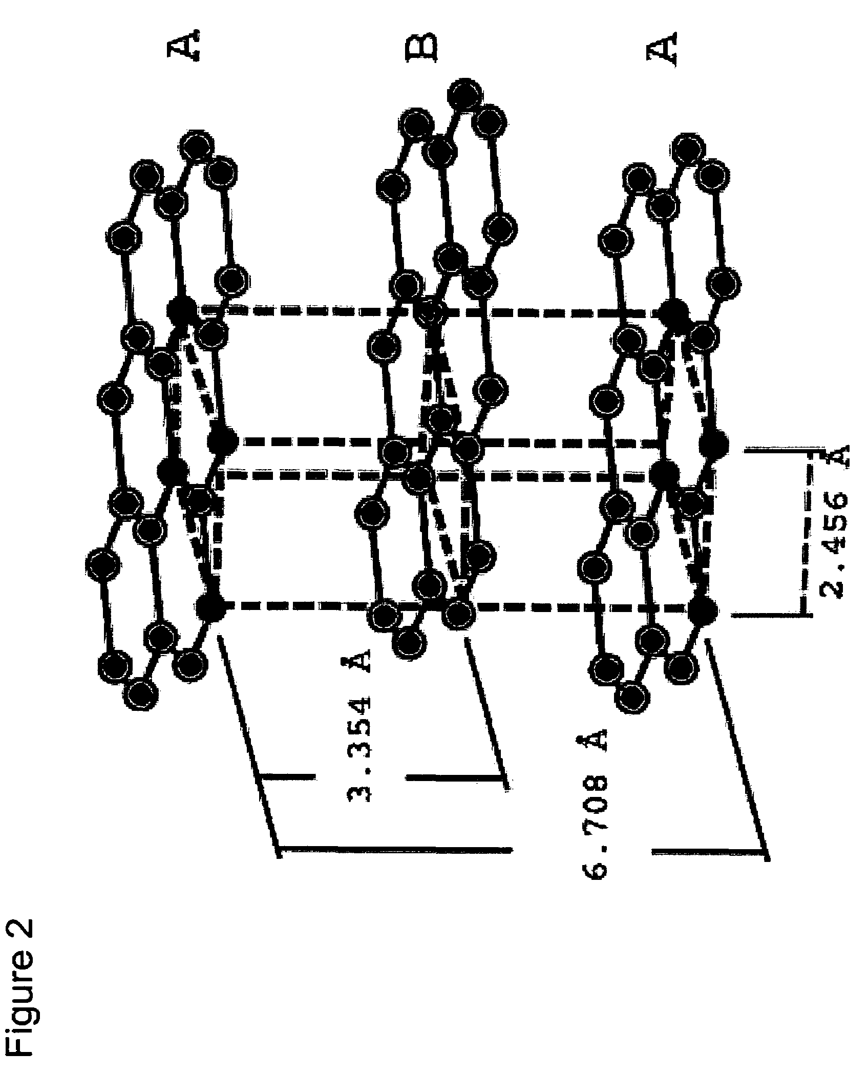
[0026]Graphite is anisotropic with respect to thermal conductivity. The thermal conductivity in the basal plane of graphite (the so called graphitic plane) is extraordinarily high. Typically, the conductivity parallel to the basal plane is about 2000 W / m-K. These values are comparable to those of diamond, the best-known thermal conductor. However, values for the conductivity perpendicular to the graphitic plane are typically about two orders of magnitude lower, or roughly 10 W / m-K. FIG. 2 illustrates the basal plane of graphite. The basal plane is defined by the plane of the C-C covalent bonds.

[0027]Thermal...


PUM

PropertyMeasurementUnit
lengthaaaaaaaaaa
thicknessesaaaaaaaaaa
particle sizeaaaaaaaaaa

Abstract

The present invention relates generally to thermally-conductive pastes for use with integrated circuits, and particularly, but not by way of limitation, to self-orienting microplates of graphite.

Description

FIELD OF THE INVENTION[0001]The present invention relates generally to thermally-conductive pastes for use with integrated circuits, and particularly, but not by way of limitation, to self-orienting microplates of graphite.BACKGROUND[0002]The information provided below is not admitted to be prior art to the present invention, but is provided solely to assist the understanding of the reader.[0003]Computer chips operate at ever greater power densities as circuits are packed more and more closely together. This higher power density can not be effectively accommodated by traditional methods of cooling. Higher power consumption without concomitant heat removal leads to higher chip operating temperatures which can result in severe reliability, performance, and lifetime concerns. FIG. 1 shows a schematic of a conventional cooling solution comprising a chip mounted on a ceramic module and a heat transfer paste applied to the top surface of the chip and squeezed against a heat sink. This cre...

Claims


Application Information

Patent Timeline
Patent Type & Authority Patents(United States)
IPC IPC(8): H01B1/04
CPCB82Y30/00H01L23/373H01L23/3736H01L23/40H01L23/3733Y10S977/788Y10T156/10H01L2224/16225H01L2924/00014H01L2924/00011Y10T428/24994H01L2224/0401
Inventor HOUGHAM, GARETHLAURO, PAUL A.SUNDLOF, BRIAN R.GELORME, JEFFREY D.
Owner GLOBALFOUNDRIES U S INC
Why Eureka
Try Eureka