Device for measuring an electric current

Inactive Publication Date: 2008-04-01
ITRON GLOBAL SARL
View PDF8 Cites 2 Cited by
  • Summary
  • Abstract
  • Description
  • Claims
  • Application Information

AI Technical Summary

Benefits of technology

[0010]The aim of the present invention is to provide a device for measuring an electric current of reduced size and cost, permitting easy adaptation to all types of t

Problems solved by technology

In addition, this compactness helps limit the quantity of material utilised to create the shielding surrounding the

Method used


Image

  • Device for measuring an electric current
  • Device for measuring an electric current
  • Device for measuring an electric current

Examples


first embodiment

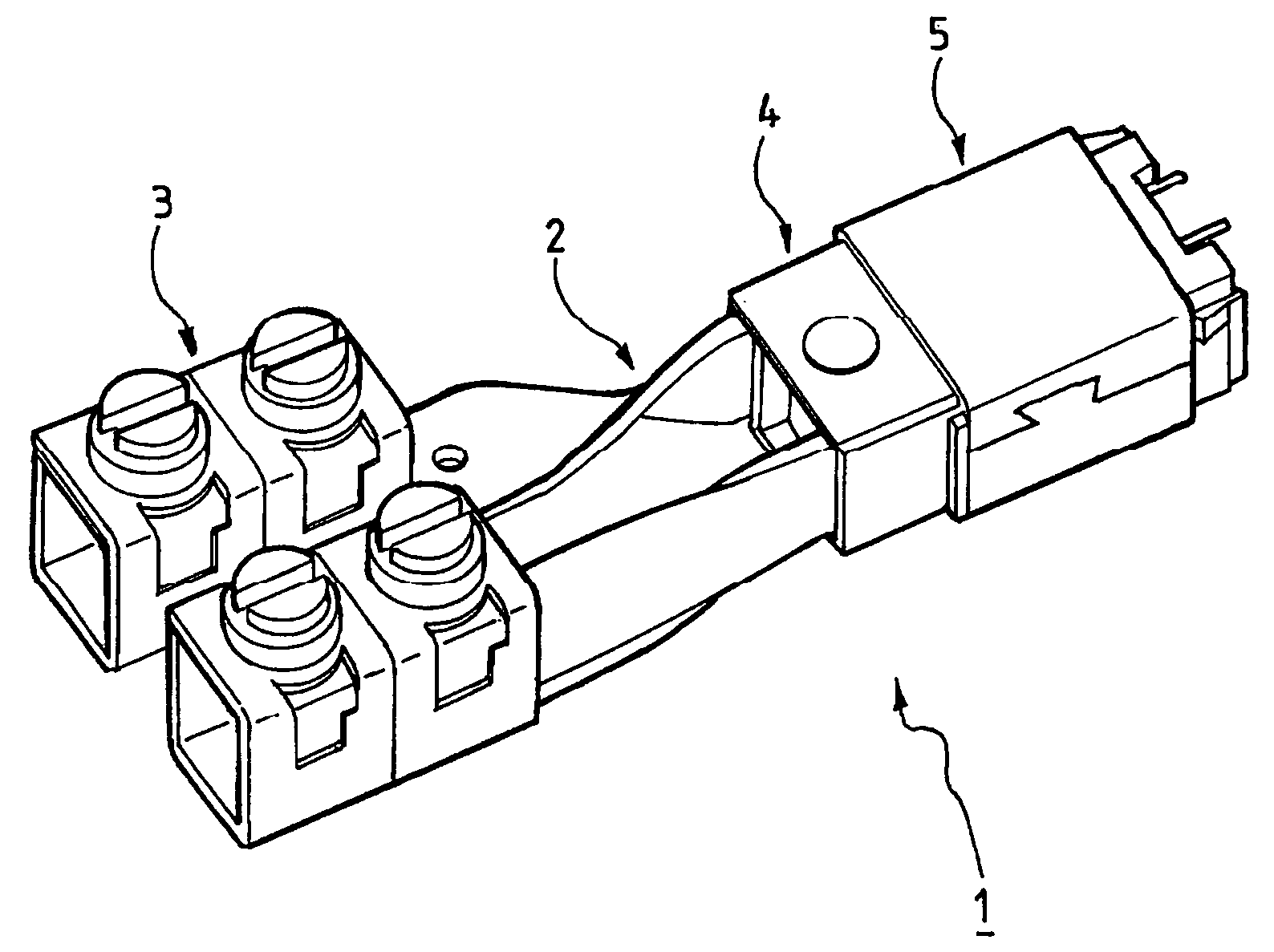
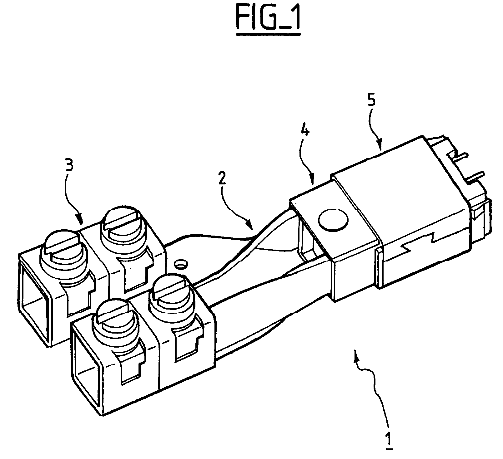
[0046]FIG. 3 illustrates a primary conductor used in a device according to the present invention, and has already been described in relation to FIGS. 1 and 2.

second embodiment

[0047]FIG. 4 illustrates a primary conductor 100 used in a device according to the present invention.

[0048]The primary conductor 100 is identical to the primary conductor such as shown in FIG. 3, with the difference that its two branches 101 and 102 each have an end 101A and 102B having a semi-cylindrical shape.

[0049]These ends 101A and 102B of semi-cylindrical shape are particularly useful for penetrating into terminals having openings cylindrical in order to make electrical contact with a counter.

[0050]Of course, the invention is not limited to the particular embodiments described hereinabove.

[0051]In particular, the shape of the ends of the branches of the primary conductor has been described as being plane or semi-cylindrical, though other shapes, which can be adapted to other types of terminals, are also feasible.


PUM


Abstract

The present invention relates to a device 1 for measuring an electric current and is particularly well adapted to electricity counters. This device 1 comprises a primary conductor 2 having a general U-shape, said primary conductor comprising a core 16 substantially circular in shape centred on an axis C, said central axis, and two branches, said first 19 and second 20 branches and a secondary winding 6 sensitive to a magnetic field, said secondary winding being disposed between said first 19 and second 20 branch of said primary conductor 2. Said primary conductor 2 is a flat profile folded in a U, said first branch 19 exhibiting torsion 13 of an angle of 90° according to a first direction of torsion and said second branch 20 exhibiting torsion 12 according to an angle of 90° along a second direction of torsion.

Description

RELATED APPLICATION[0001]This application is related to and claims the benefit of priority from French Patent Application No. 03 00342, filed on Jan. 14, 2003, the entirety of which is incorporated herein by reference.FIELD OF THE INVENTION[0002]The present invention relates to a device for measuring an electric current. This device is particularly well adapted to electricity counters.BACKGROUND OF THE INVENTION[0003]Several types of current sensors can be utilised in an electricity counter and are described in FR 2 800 167.[0004]In particular, sensors with Hall effect are known, in which a Hall element is subjected to a magnetic field generated by a current in a primary winding. The Hall tension measured at the terminals of the Hall element is proportional to the current crossing this primary winding.[0005]Another type of known sensor makes use of a transformer with mutual inductance. This type of sensor comprises for example a primary conductor having a the general form of an open...

Claims


Application Information

Patent Timeline
IPC IPC(8): G01R19/00G01R15/18G01R1/00
CPCG01R15/18G01R15/181G01R15/183
Inventor GUILLON, JEAN-LOUIS
Owner ITRON GLOBAL SARL
Why Eureka
Try Eureka