Unlock instant, AI-driven research and patent intelligence for your innovation.
Communication method, communication system, and communication terminal
Inactive Publication Date: 2008-04-01
SONY CORP
View PDF12 Cites 6 Cited by
Summary
Abstract
Description
Claims
Application Information
AI Technical Summary
This helps you quickly interpret patents by identifying the three key elements:
Problems solved by technology
Method used
Benefits of technology
Benefits of technology
[0013]As described above, according to the conventional communication methods, it is difficult to satisfy all demands for using the real time access of transmitting and receiving real time data at real time and the random access of transmitting and receiving data generated at random at random timing and improving the throughput.
[0100]When transmitting a compressed signal by rate variable compression method, it is possible to cope with changes of the packet length due to deviation of the rate only by setting a channel corresponding to, for example, average transmission rate.
Problems solved by technology
However, the above-mentioned transmission methods are incapable of satisfying all these demands.
However, if it is found that other communication terminal is transmitting data as a result of the aforementioned carrier detection to avoid the collision, that communication terminal cannot transmit data.
Thus, random waiting time may be sometimes needed upon transmission of data, and therefore it is difficult to always maintain the throughput in a good condition.
Because the CSMA method does not ensure the communication sequence unlike the TDMA method, transmission of real time data such as voice data and image data cannot be ensured.
However, because many time slots for non-use are generated in transmitting data generated at random such as computer data, this method is not effective.
Therefore, the TDMA method is not suitable for random access.
Because the TDMA method does not carry out the carrier detection, if a communication terminal not obeying the TDMA method is connected to the same channel, a collision of transmission may not be avoided.
That is, this method cannot coexist with a communication terminal employing other communication method than the TDMA method.
Method used
Image
Click on the blue label to locate the original text in one second.
Reading with bidirectional positioning of images and text.
Examples
first embodiment
[About One-Way Communication]
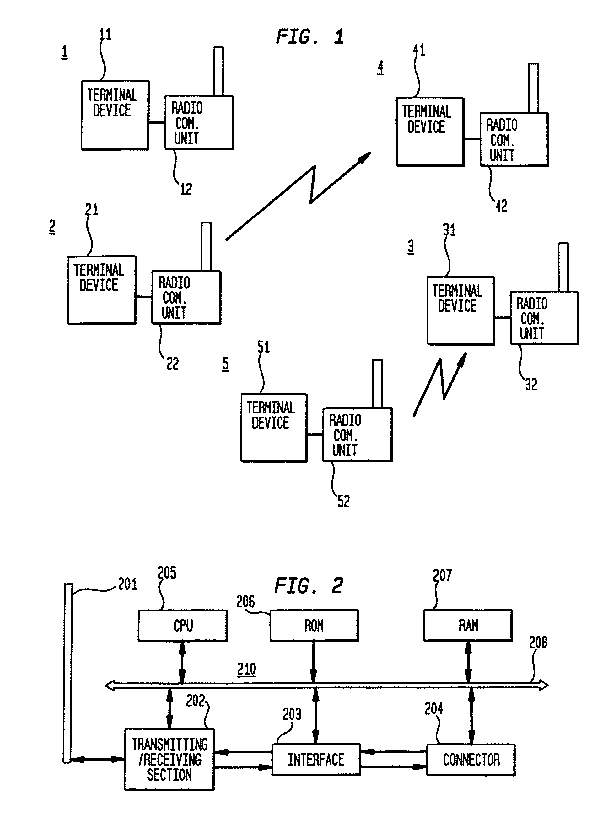
[0119]FIG. 1 is a diagram for explaining the structure of LAN of this embodiment. The LAN for use in this embodiment has so-called Peer to Peer structure in which no server dedicated unit is provided and communication units connected to this network are on the same position.
[0120]In FIG. 1, terminal devices 11, 21, 31, 41, 51 are personal computers or work stations. Radio communication units (LAN unit) 12, 22, 32, 42, 52, which are communication terminals of this embodiment, are connected to these terminal devices 11, 21, 31, 41, 51 so as to form LAN terminal devices 1, 2, 3, 4, 5. As a result, communication is enabled between the respective LAN terminal devices.
[0121]In the LAN of this embodiment, the LAN terminal devices 1, 2, 3, 4, 5 use a transmission method like the CSMA method whereby the LAN devices receive and transmit data through packet transmission and detect a carrier prior to packet transmission in order to avoid a collision in transmission ...
second embodiment
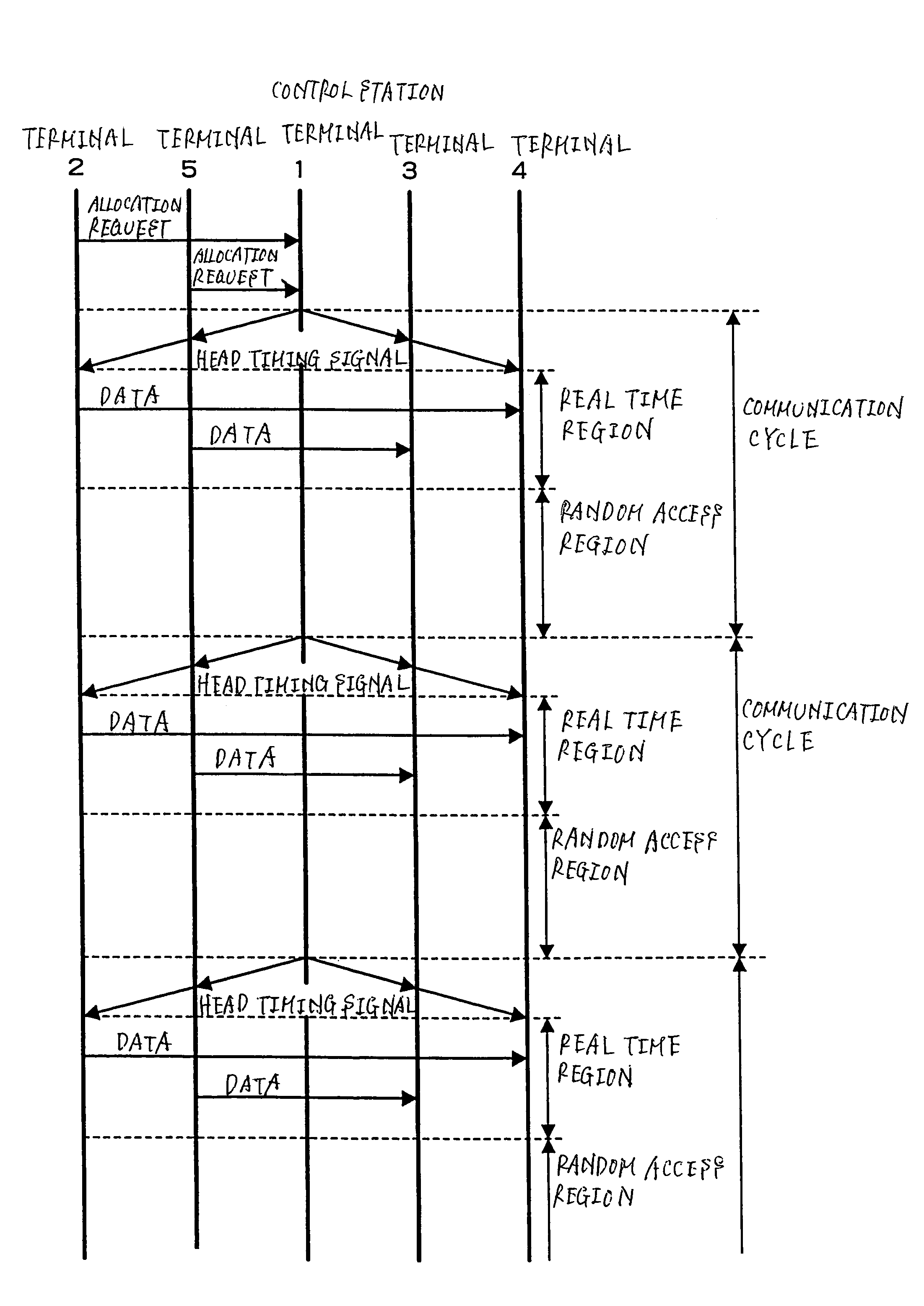
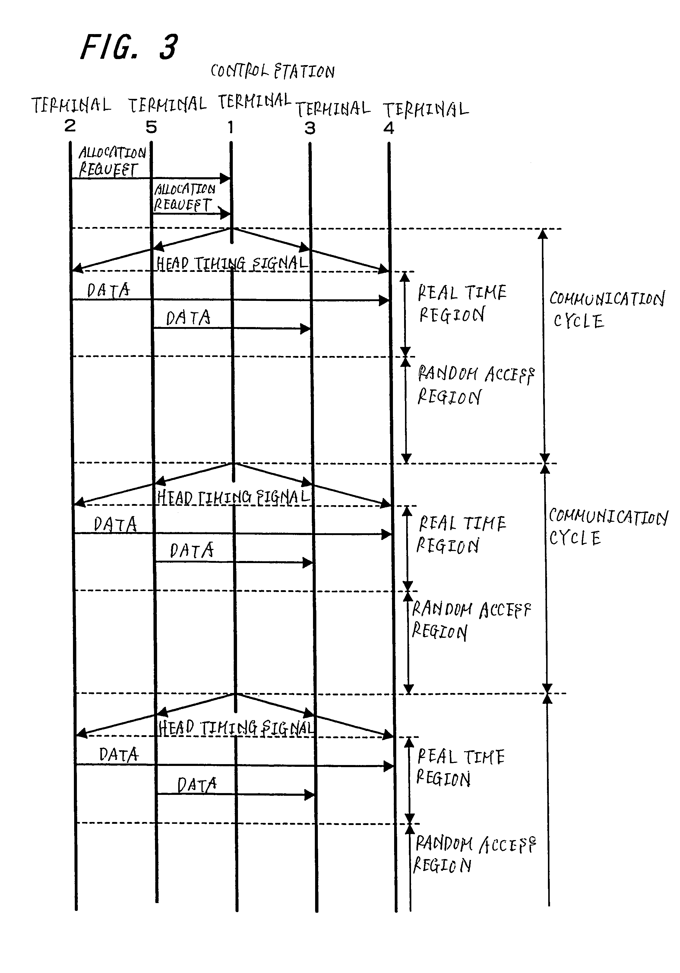
[0211]According to the aforementioned first embodiment, each LAN terminal device avoids a collision of use of the transmission path by detecting a carrier and if there is no carrier, transmits real time data at transmission timing allocated preliminarily and fixedly for each LAN terminal device in a communication cycle. And each LAN terminal device carries out random access in an interval in which no transmission timing is allocated in each communication cycle.
[0212]However, according to the method explained in the first embodiment, if there is a LAN terminal device incapable of transmitting the packet at allocated transmission timing because of mixing of disturbing signal in the transmission path, there is a possibility that collision of use of the transmission path cannot be prevented among the LAN terminal devices located subsequent to that LAN terminal device.
[0213]In the LAN system of the first embodiment described with reference to FIG. 1, it is assumed, for example, that timi...
PUM
Abstract
In order to enable use of both real time access and random access and to achieve improvement of throughput of a communication device and a communication network, a LAN terminal device (1), acting as a control station, allocates communication timing corresponding to a communication timing allocation request from a first LAN unit (2) and a second LAN unit (5) intending to transmit real time data and notifies each LAN terminal device connected to the same network of information indicating this allocated communication timing. A communication terminal of the requester transmits data through a real time region based on communication timing allocated thereto and random data is transmitted through a random access region.
Description
TECHNICAL FIELD[0001]The present invention relates to a communication method in which various devices such as computer terminals and peripheral devices are connected through network so as to achieve communication between the devices connected through this network, a communication system and a communication terminal.BACKGROUND ART[0002]Various communication methods which allow communication to be carried out without link-block of transmissions in the same channel are employed in a network in which the same channel is shared by plural communication terminals. For example, CSMA (Carrier Sense Multiple Access) method, TDMA (Time Division Multiple Access) method, polling method and the like are employed.[0003]In the CSMA method, transmission data is put into a packet of a predetermined size and transmitted. A communication terminal using this method transmits the packet using a carrier having a predetermined frequency. Upon transmission of the packet, the carrier is detected (the term ca...
Claims
Application Information
Patent Timeline
Application Date:The date an application was filed.
Publication Date:The date a patent or application was officially published.
First Publication Date:The earliest publication date of a patent with the same application number.
Issue Date:Publication date of the patent grant document.
PCT Entry Date:The Entry date of PCT National Phase.
Estimated Expiry Date:The statutory expiry date of a patent right according to the Patent Law, and it is the longest term of protection that the patent right can achieve without the termination of the patent right due to other reasons(Term extension factor has been taken into account ).
Invalid Date:Actual expiry date is based on effective date or publication date of legal transaction data of invalid patent.

