System and method for re-routing signals between memory system components

a memory system and signal technology, applied in the field of memory systems, can solve the problems of insufficient substitution procedure, low speed of memory controllers and memory devices, and increase in operating speed that cannot keep pace with increase in processor operating speed,

Active Publication Date: 2008-04-01
MICRON TECH INC
View PDF27 Cites 63 Cited by
  • Summary
  • Abstract
  • Description
  • Claims
  • Application Information

AI Technical Summary

Problems solved by technology

Although the operating speed of memory devices has continuously increased, this increase in operating speed has not kept pace with increases in the operating speed of processors.
The relatively low speed of memory controllers and memory devices limits the communication bandwidth between the processor and the memory devices.
However, if two or more bit-lanes have become inoperable, this substitution procedure will not suffice unless two extra bit-lanes have been provided.

Method used


Image

  • System and method for re-routing signals between memory system components
  • System and method for re-routing signals between memory system components
  • System and method for re-routing signals between memory system components

Examples


Embodiment Construction

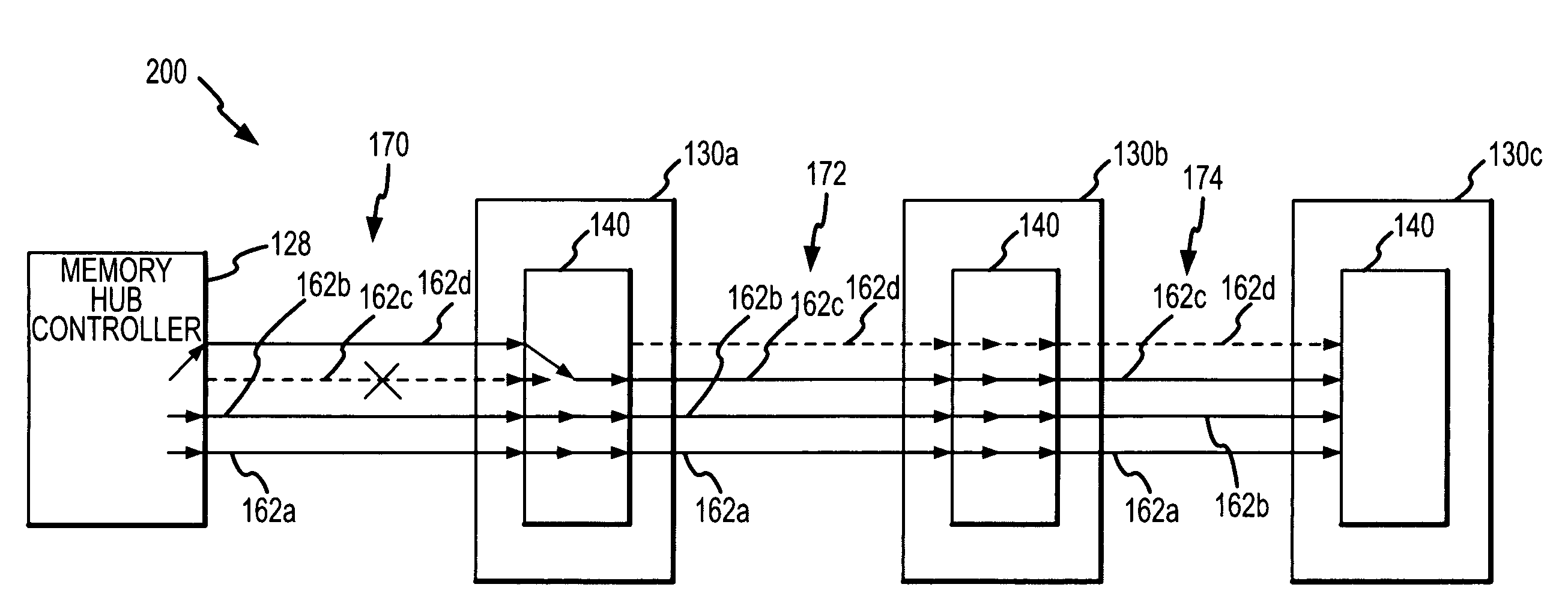
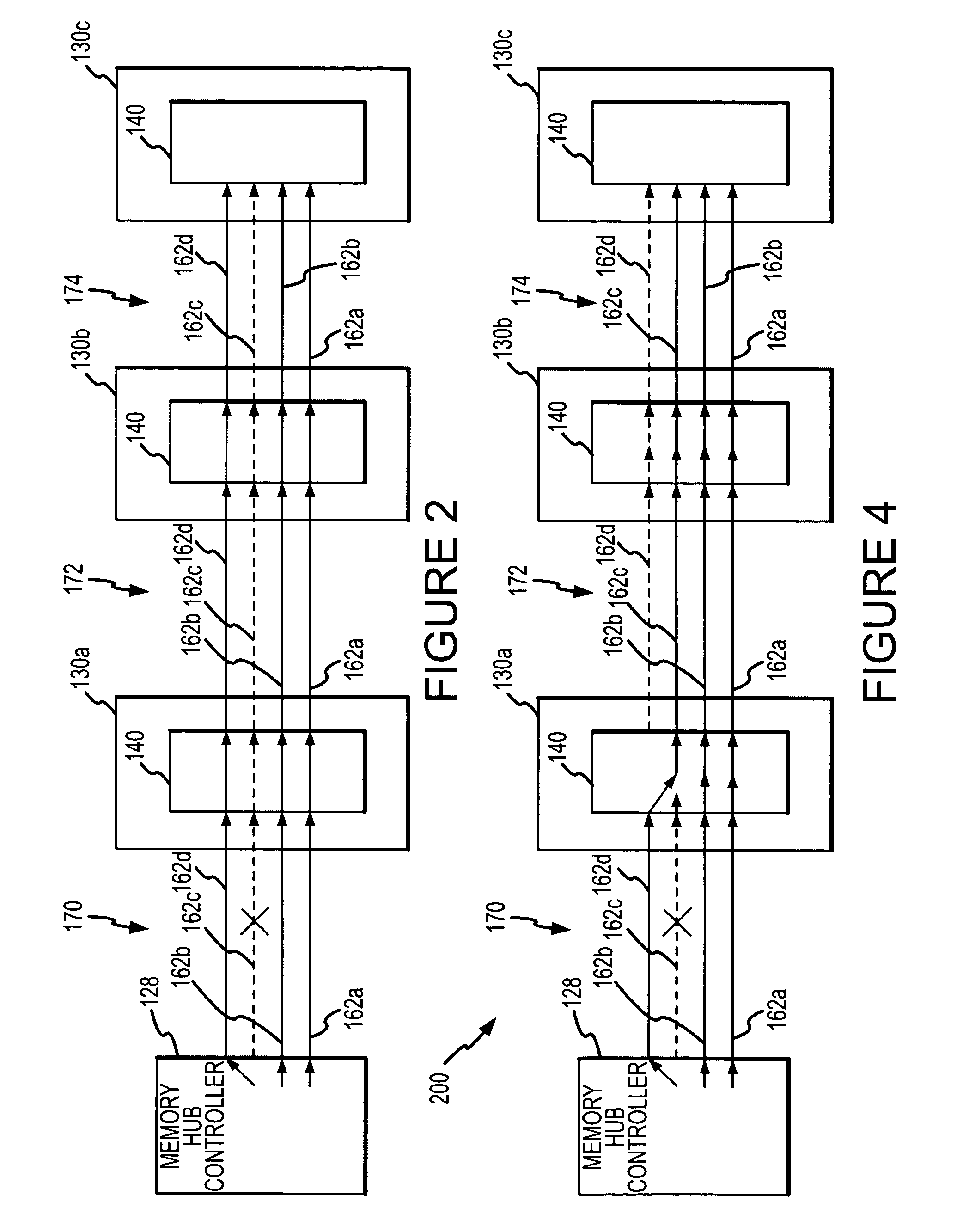
[0025]One example of portion of a computer system 200 having a memory hub architecture that can continue to operate in the event multiple bit lanes become defective is shown in FIG. 4. The computer system 200 may have a large number of downstream bit lanes 162 and a large number of upstream bit lanes 164, although only 4 downstream bit lanes 162a-d are shown in FIG. 4 for purposes of simplicity and clarity. As shown in FIG. 4, the bit-lane 162c in the first bit-line segment 170 has become defective. This is the same defect as in the computer system 100 shown in FIG. 2. As in the computer system shown in FIG. 2, the memory hub controller 128 re-routes the signals to and from the bit-lane 162c in the first bit-line segment 170 so they now pass through the bit-lane 162d. However, the memory hub 140 in the first memory module 130a does not simply couple the first segment 170 of the bit-lane 162d to the second segment 172 of the bit lane 162d. Instead, the memory hub 140 in the first mem...


PUM


Abstract

A plurality of memory modules used in a computer system each include a memory hub that is connected to a plurality of memory devices. The memory modules are connected to each other in series so that signals are coupled between the memory modules and the memory hub controller through any intervening memory modules. The signals are coupled to and from the memory modules through high-speed bit-lanes. In the a bit-lane connected to any of the memory hubs is inoperative, the memory hub re-routes signals that would be coupled through the inoperative bit-lane to an adjacent bit lane. When the signal reaches a memory hub in which the bit-lane is no longer inoperative, the memory hub routes the signal back to the original bit lane. In this manner, multiple bit-lane failures can be accommodated using a signal extra bit-lane.

Description

TECHNICAL FIELD[0001]This invention relates to memory systems, and, more particularly, to a memory system having a memory controller or the like coupled to several memory modules, each of which may have a memory hub architecture.BACKGROUND OF THE INVENTION[0002]Computer systems use memory devices, such as dynamic random access memory (“SDRAM”) devices, to store instructions and data that are accessed by a processor. In a typical computer system, the processor communicates with the system memory through a processor bus and a memory controller. The processor issues a command, such as a read command, and an address designating the location from which data or instructions are to be read. The memory controller uses the command and address to generate appropriate command signals as well as row and column addresses, which are applied to the system memory. In response to the commands and addresses, data are transferred between the system memory and the processor. The memory controller is of...

Claims


Application Information

Patent Timeline
Patent Type & Authority Patents(United States)
IPC IPC(8): G06F12/00G11C5/00G06F11/00
CPCG06F11/2007G11C5/00G06F12/00G06F13/10
Inventor ERDMANN, MICHAEL
Owner MICRON TECH INC
Why Eureka
Try Eureka