Heat sink with microchannel cooling for power devices

a technology of microchannel cooling and power devices, which is applied in the direction of cooling/ventilation/heating modification, semiconductor/solid-state device details, semiconductor devices, etc., can solve the problems of increasing the difficulty of cooling power semiconductor devices, manufacturing difficulties, and natural and forced air cooling schemes that cannot handle heat flux

Inactive Publication Date: 2008-04-08
GENERAL ELECTRIC CO
View PDF24 Cites 131 Cited by
  • Summary
  • Abstract
  • Description
  • Claims
  • Application Information

AI Technical Summary

Problems solved by technology

The development of higher-density power electronics has made it increasingly more difficult to cool power semiconductor devices.
When device temperatures are limited to 50 K increases, natural and forced-air cooling schemes can only handle heat fluxes up to about one (1) W / cm2.
Heat pipes, impingement sprays, and liquid boiling are capable of larger heat fluxes, but these techniques can lead to manufacturing difficulties and high cost.
An additional problem encountered in conventional cooling of high heat flux power devices is non-uniform temperature distribution across the heated surface.
This is due to the non-uniform cooling channel structure, as well as the temperature rise of the cooling fluid as it flows through long channels parallel to the heated surface.
In most microchannel designs, the increased heat transfer is offset by increased pressure losses in the small-scale channels, which results in increased pumping needs.
However, the manufacture of this heat sink is somewhat difficult, as micro-channels and larger fluid supply / return passages must be first machined on individual copper laminations, which are then assembled in a stack.
The holes introduce additional turbulence in the liquid, enhancing the heat transfer, but also resulting in a higher pressure drop.
Based on published thermal performance results, the design of Schultz-Harder et al. is less effective than that of Valenzuela et al, but it is still better than conventional heat sinks.
Although implementation of microchannels directly in the semiconductor device's substrate may be suitable for low-voltage RF applications, it is not practical for the switching power inverter applications.
Implementation of the micro-channels at the bottom of the device would be impractical for several reasons.
The implementation would interfere with the electrical interconnect to other circuit components, the implementation would expose cooling fluid to high voltage and put severe restrictions on suitable fluids and / or necessitate de-ionization equipment, and the implementation would exacerbate electromagnetic interference (EMI) problems due to cooling fluid becoming conduction path for high frequency currents.
There are several disadvantages of this design.
Scalability to larger heat sink sizes is limited by fluid manifolding in a vertical direction and it may lead to excessive heat sink thickness.
Finally, Mundinger fails to address implementation of electrical isolation between the semiconductor power devices and the cooling fluid.
One drawback of this approach is that thermal performance of the porous metal pad is less effective.

Method used


Image

  • Heat sink with microchannel cooling for power devices
  • Heat sink with microchannel cooling for power devices
  • Heat sink with microchannel cooling for power devices

Examples


Embodiment Construction

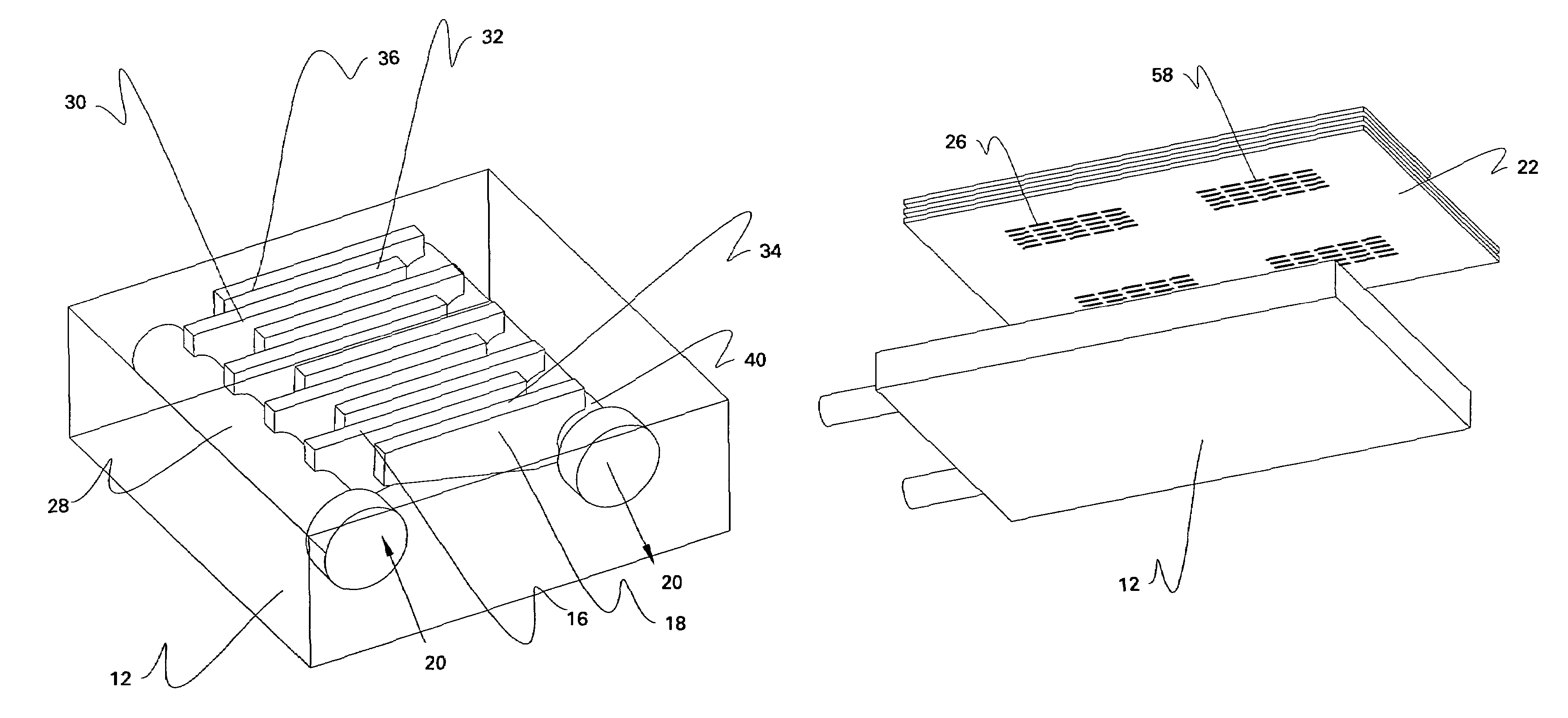
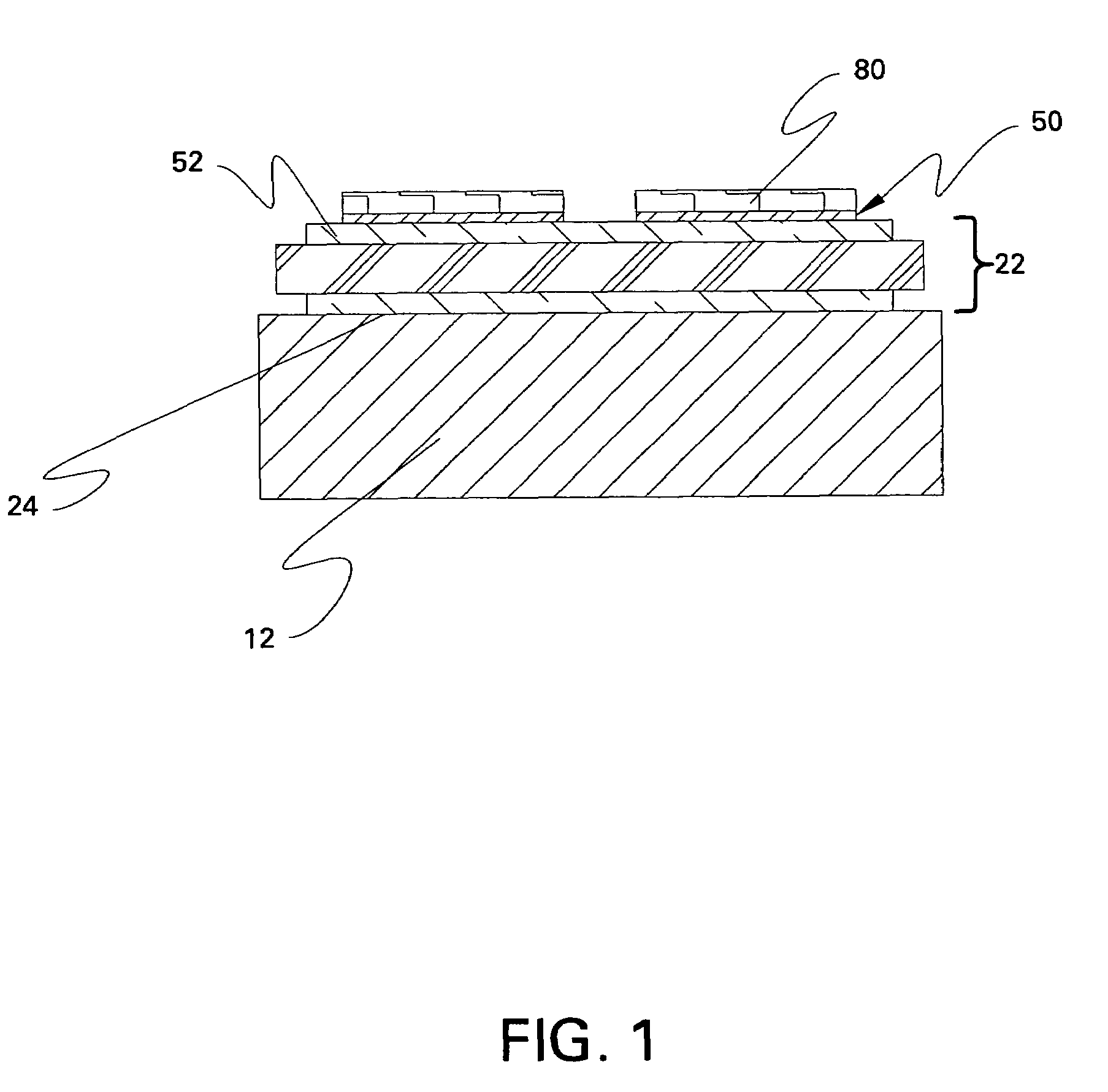
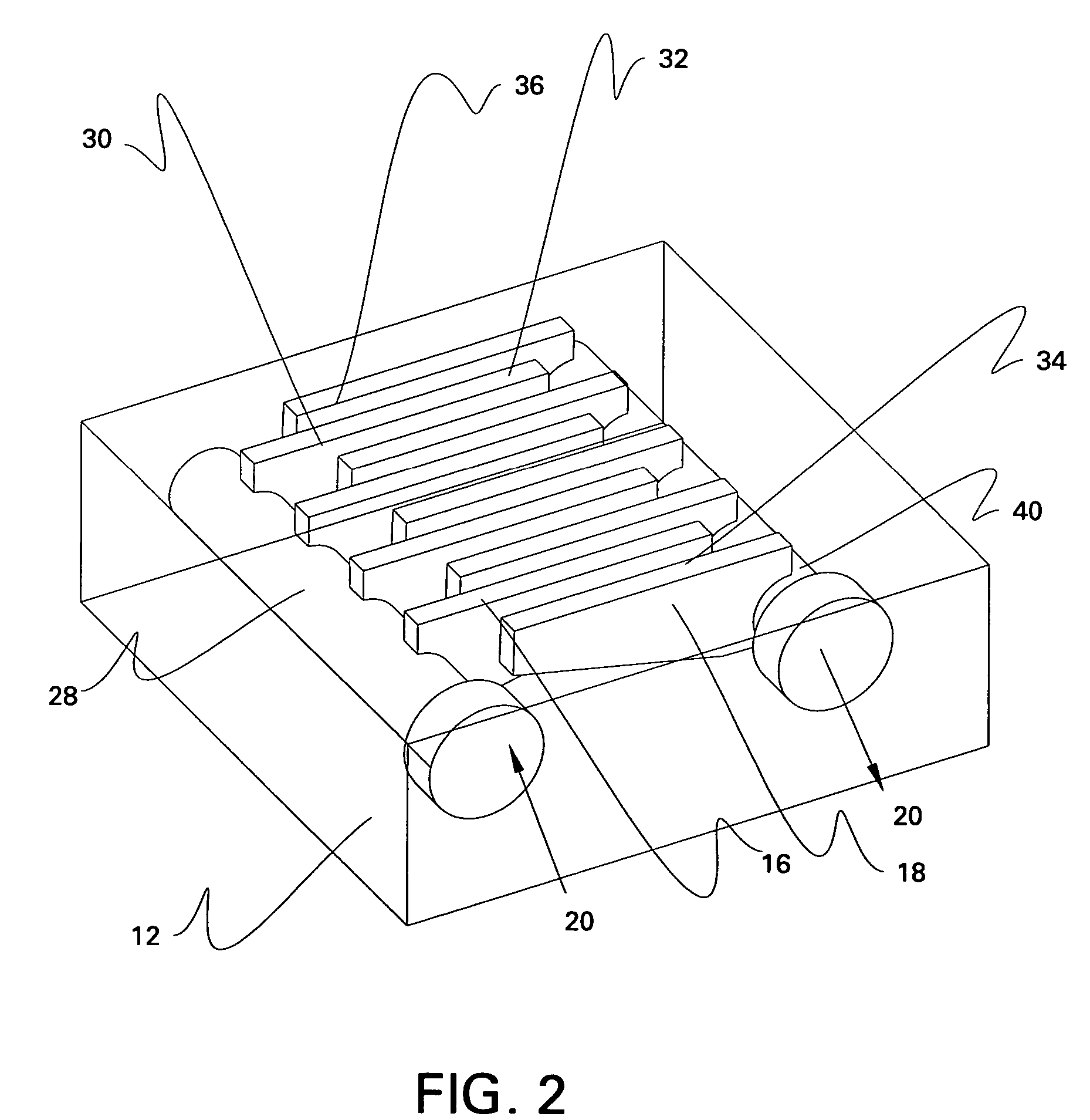
[0029]An apparatus 10 for cooling at least one heated surface 50 is described with reference to FIGS. 1-3 and 5. As shown, for example, in FIG. 1, apparatus 10 includes a base plate 12, which is shown in greater detail in FIG. 2. As shown, for example, in FIG. 2, base plate 12 defines a number of inlet manifolds 16 and a number of outlet manifolds 18. The inlet manifolds 16 are configured to receive a coolant 20, and the outlet manifolds 18 are configured to exhaust the coolant. As indicated in FIG. 2, for example, inlet and outlet manifolds 16, 18 are interleaved. As indicated in FIG. 1, apparatus 10 further includes at least one substrate 22 having a inner surface 24 and an outer surface 52, the inner surface 24 being coupled to base plate 12. As shown for example in FIGS. 3 and 5, the inner surface 24 features a number of microchannels 26 configured to receive the coolant from inlet manifolds 16 and to deliver the coolant to outlet manifolds 18. Microchannels 26 are oriented subs...


PUM


Abstract

An apparatus for cooling at least one heated surface includes a base plate defining a number of inlet and outlet manifolds. The inlet manifolds are configured to receive a coolant, and the outlet manifolds exhaust the coolant. The inlet and outlet manifolds are interleaved. The apparatus also includes at least one substrate having inner and outer surfaces. The inner surface is coupled to the base plate and defines a number of microchannels that receive the coolant from the inlet manifolds and deliver the coolant to the outlet manifolds. The microchannels are oriented substantially perpendicular to the inlet and outlet manifolds. The outer surface is in thermal contact with the heated surface. The apparatus also includes an inlet plenum that supplies the coolant to the inlet manifolds, and an outlet plenum that exhausts the coolant from the outlet manifolds. The inlet plenum and outlet plenum are oriented in a plane of the base plate.

Description

CROSS REFERENCE TO RELATED APPLICATIONS[0001]This application is related to commonly assigned, copending U.S. patent application No. 10 / 998,798, now U.S. Pat. No. 7,327,024 entitled “Power module, phase leg, and three-phase inverter,” Stevanovic et al., filed concurrently herewith, which patent application is incorporated by reference herein in its entirety.BACKGROUND[0002]The invention relates generally to an apparatus for cooling a heated surface and, more particularly, to a heat sink with microchannel cooling for semiconductor power devices.[0003]The development of higher-density power electronics has made it increasingly more difficult to cool power semiconductor devices. With modern silicon-based power devices capable of dissipating up to 500 W / cm2, there is a need for improved thermal management solutions. When device temperatures are limited to 50 K increases, natural and forced-air cooling schemes can only handle heat fluxes up to about one (1) W / cm2. Conventional liquid coo...

Claims


Application Information

Patent Timeline
Patent Type & Authority Patents(United States)
IPC IPC(8): H05K7/20
CPCH01L23/473H01L2924/13055H01L2924/1305H01L2924/13091H01L2224/32225H01L2924/00
Inventor STEVANOVIC, LJUBISA DRAGOLJUBSOLOVITZ, STEPHEN ADAM
Owner GENERAL ELECTRIC CO
Why Eureka
Try Eureka