Heating unit

a heating unit and airflow technology, applied in the field of heating units, can solve problems such as freezing of occupants, and achieve the effects of improving airflow uniformity, flat design, and being physically compa

Active Publication Date: 2008-04-08
EBM PAPST ST GEORGEN & -
View PDF46 Cites 36 Cited by
  • Summary
  • Abstract
  • Description
  • Claims
  • Application Information

AI Technical Summary

Benefits of technology

[0006]It is therefore an object of the invention to provide a novel heating unit having improved uniformity of airflow through its heating element. This object is achieved by a heating unit equipped with a radial fan, a curved housing surrounding the fan and defining a pressure chamber, a heating element arranged near the air outlet, and airflow-guiding elements arranged between the pressure chamber and the heating element. A heating unit of this kind can be physically very compact, the use of a radial fan enabling a very flat design. The use of a radial fan with a high air output allows a rapid rise in temperature to be achieved, for example in a passenger compartment.
[0007]The heating unit is advantageously implemented using a miniature or subminiature fan. Miniature fans (or mini-fans) of this kind have very small dimensions. They have historically been used chiefly in electronics for active cooling of CPU chips and the like, and combine a very compact design with low cost, sufficient service life, and high efficiency.
[0008]A preferred refinement of the invention is to place more effective obstacles in that sector, of the airflow leaving the pressure chamber, which would, in the absence of obstacles, have the higher airflow velocity. What is obtained thereby is a heating unit in which the velocity of the air that flows through the heating element differs only slightly at the various locations of that heating element. This is very advantageous especially when PTC (Positive Temperature Coefficient) heating elements are used, since if the flow velocity is particularly high at one location, the electrical resistance there decreases; and if the flow velocity is low, this results in local overheating, and thus in a corresponding increase in the electrical resistance, so that little heat is generated there. With the invention, it is possible to keep the resistance of a PTC heating element of this kind largely within an optimal working range and, in this manner, to generate sufficient heat, even with a small fan. The air flow generated by the radial fan is influenced by air-directing elements in such a way that the differing flow velocities of the air flowing out of the radial fan are made substantially uniform.

Problems solved by technology

This means that less waste heat is available to heat such vehicles; in other words, if additional actions are not taken, their occupants freeze when the weather is cold.

Method used


Image

  • Heating unit
  • Heating unit
  • Heating unit

Examples


Embodiment Construction

[0022]In the description that follows, the terms “left,”, “right,”“upper,” and “lower” refer to the respective figure of the drawings, and can vary from one figure to the next as a function of a particular selected orientation (portrait or landscape format). Identical or identically functioning parts are labeled in the various Figures with the same reference characters, and are usually described only once.

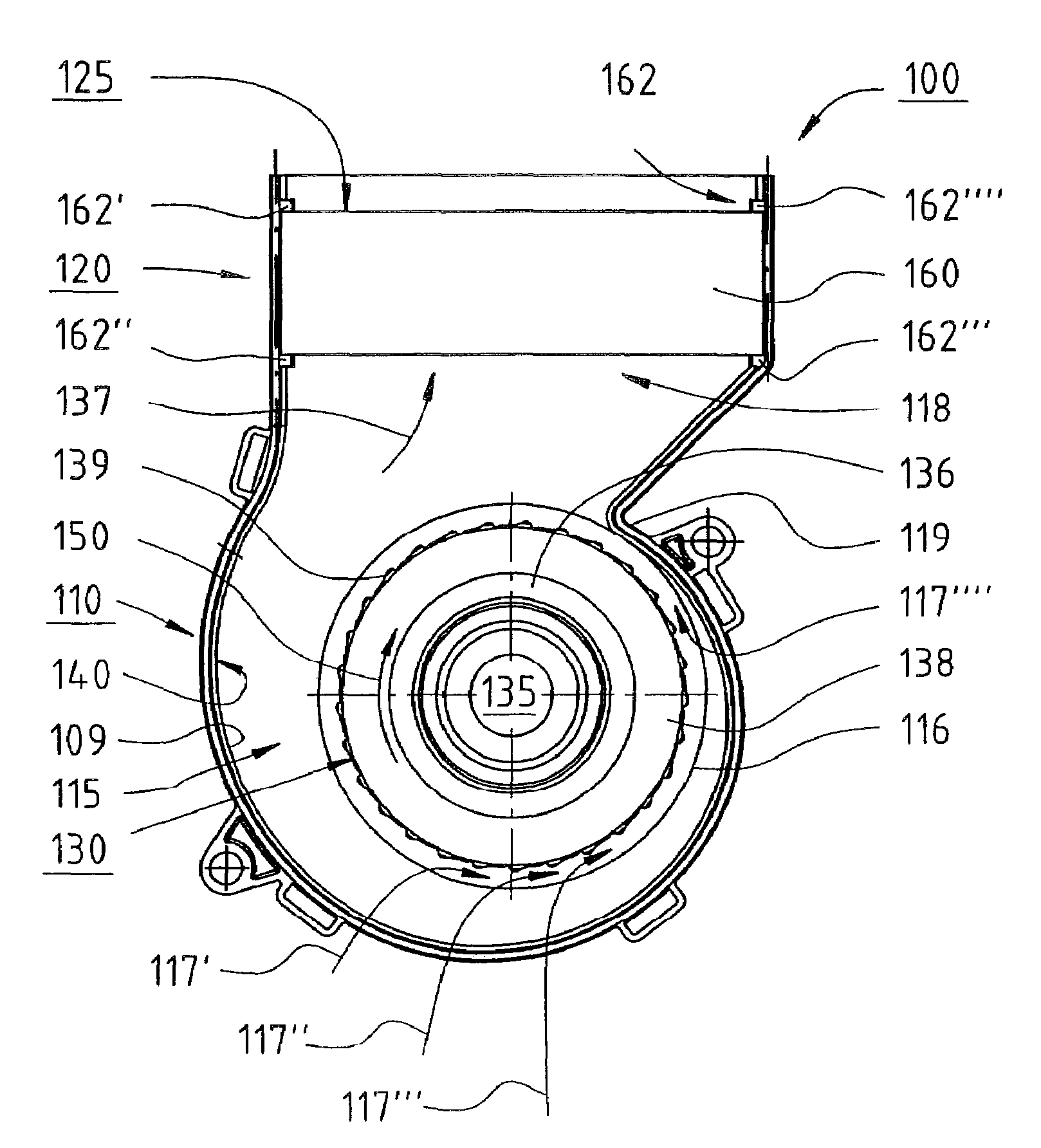
[0023]FIG. 1 is a longitudinal section through a heating unit 100 (shown without its upper cover), viewed from a front side, according to a preferred embodiment of the invention. Heating unit 100 has a fan housing 110 and a connecting part 120. Implemented in the interior of fan housing 110 is a pressure chamber 115 in which a radial fan wheel 130 is arranged. Fan housing 110 and connecting part 120, which latter comprises an electrical heating element 125, are connected to one another. The housing has a spiral-shaped outer wall 109 and is therefore referred to as a spiral housing ...


PUM


Abstract

A heating unit for a vehicle features a radial fan (100) having a housing (110), which housing has an air inlet (116) and an air exit opening (118). The heating unit has an air-directing device (140) that guides an air flow in a pressure chamber (115) of the housing (110) to the exit opening (118). Arranged in the housing (110) is a radial fan wheel (130) that serves to generate a flow from the air inlet (116) via the pressure chamber (115) to the air exit opening (118). Also provided is an electrical heating element, e.g. a PTC (Positive Temperature Coefficient) heating element (125), that serves to transfer heat to the air flow generated by the fan. Air-directing elements (632, 634, 636, 638) are provided between the exit opening (118) and the heating element (125), in order to generate an air flow having a more uniform (680) velocity distribution.

Description

CROSS-REFERENCE[0001]This application claims priority from German application DE 20 2005 012 259.9 filed 28 Jul. 2005, the entire contents of which is hereby incorporated by reference.FIELD OF THE INVENTION[0002]The invention relates to a heating unit, particularly adapted for use in vehicles.BACKGROUND[0003]Vehicles of more recent design have drive units whose efficiency is very much improved as compared with earlier engines. This means that less waste heat is available to heat such vehicles; in other words, if additional actions are not taken, their occupants freeze when the weather is cold. This is particularly the case for diesel vehicles, but also for vehicles having fuel cell drive systems, for light aircraft, and for gasoline-powered vehicles with a hybrid drive system.[0004]Additional heating units, which are operated in some cases with fuel, and in other cases with electricity, are therefore used. For example, by means of a small electric heating unit, heated air can be blo...

Claims


Application Information

Patent Timeline
Patent Type & Authority Patents(United States)
IPC IPC(8): B60L1/02
CPCB60H1/00471B60H1/2225B60H2001/229
Inventor ANGELIS, WALTER GEORGWINKLER, WOLFGANG ARNO
Owner EBM PAPST ST GEORGEN & -
Why Eureka
Try Eureka