Rotation detecting device using magnetic sensor

a magnetic sensor and rotation detection technology, applied in the direction of mechanical conversion of sensor output, galvano-magnetic devices, instruments, etc., can solve the problem that the magnetic vector change may become insufficient for the magneto-resistance sensor to provide sensor signals

Inactive Publication Date: 2008-04-08
DENSO CORP
View PDF11 Cites 61 Cited by
  • Summary
  • Abstract
  • Description
  • Claims
  • Application Information

AI Technical Summary

Benefits of technology

[0008]Therefore, an object of the invention is to provide an improved rotation detecting device that can provide sufficient magnitude of sensor signals without work for precisely positioning the sensor chip relative to the rotating object.

Problems solved by technology

However, if the sensor chip is not correctly positioned relative to the gear teeth, the magnitude of change in the magnetic vector may become insufficient for the magneto-resistance sensor to provide sensor signals.

Method used


Image

  • Rotation detecting device using magnetic sensor
  • Rotation detecting device using magnetic sensor
  • Rotation detecting device using magnetic sensor

Examples


first embodiment

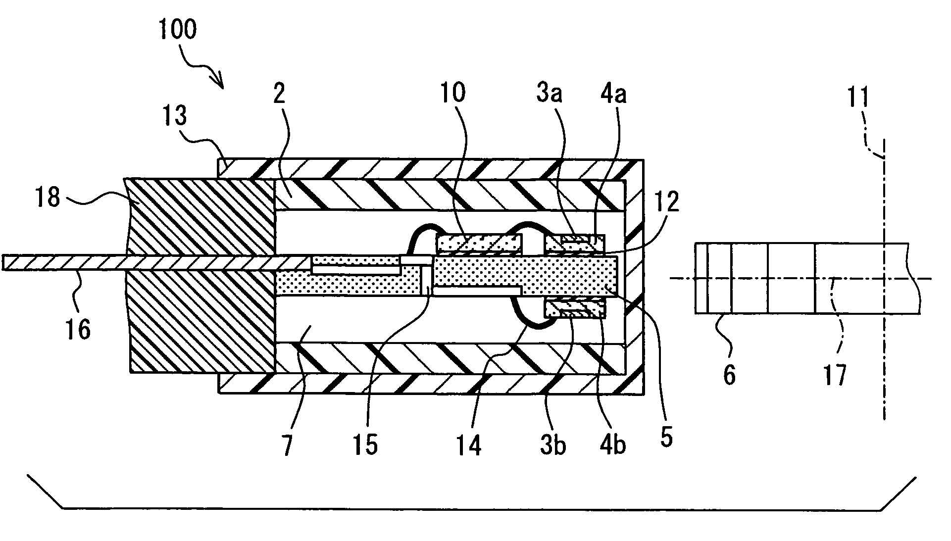
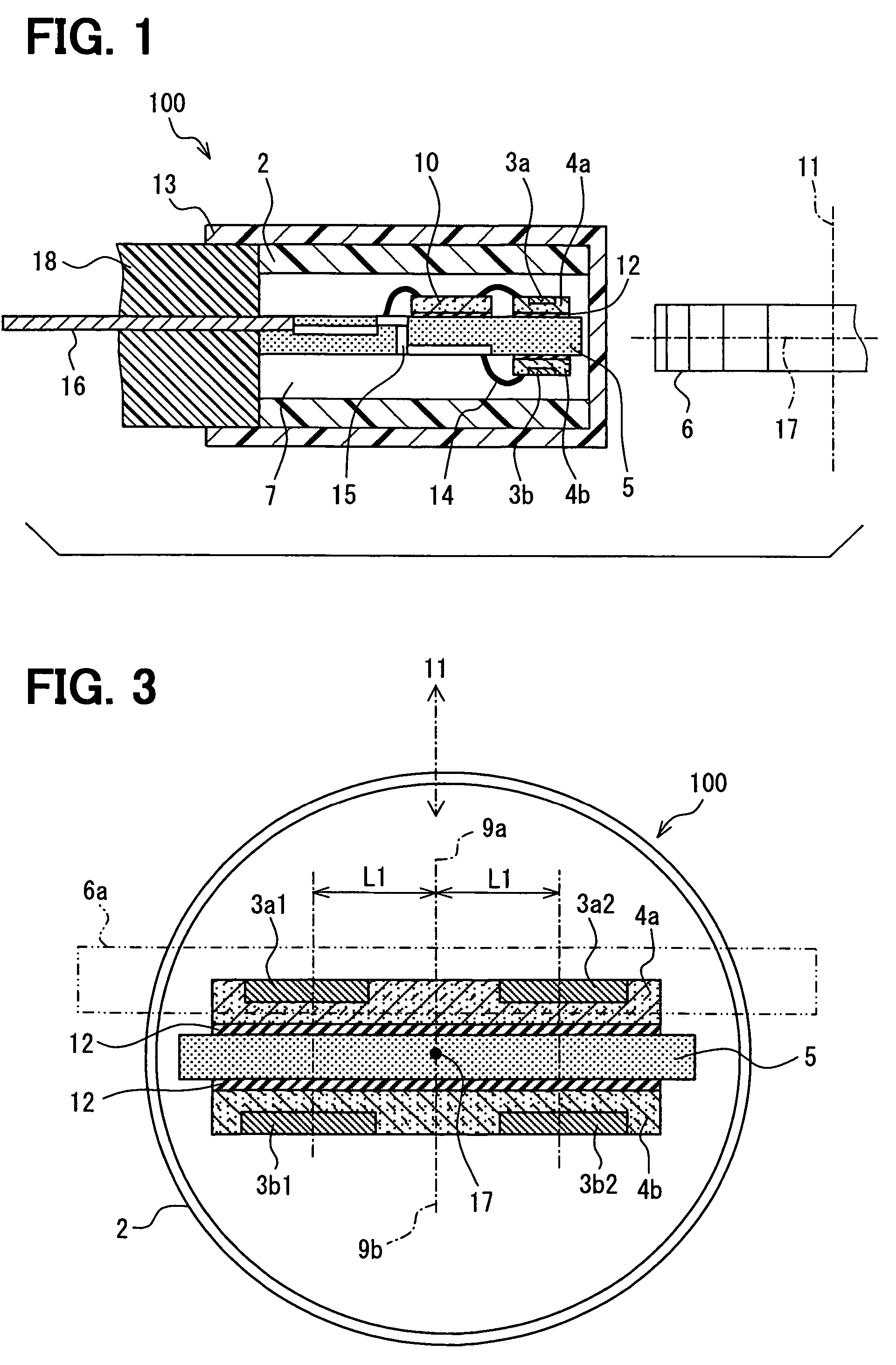
[0025]A rotation detecting device 100 according to the invention will be described with reference to FIGS. 1-3.

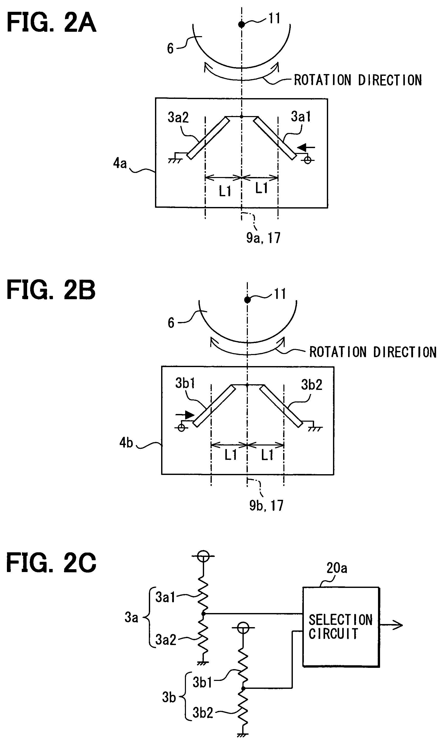
[0026]As shown in FIG. 1, the rotation detecting device 100 includes a biasing permanent magnet 2, a pair of magnetoresistance sensors 3a and 3b respectively formed on sensor chips 4a and 4b, a chip mount 5, a circuit chip 10, a cylindrical cover 13, wires 14, a terminal 15, a lead frame 16 and a cap member 18. The rotation detecting device 100 is disposed to confront a rotor or rotating object 6, which is a gear-like magnetic member having teeth along its periphery and a rotation axis 11 at its center.

[0027]The biasing permanent magnet 2 provides a biasing magnetic field that extends to the rotor 6. The biasing permanent magnet 2 is made of a bonded composite of magnet powder and organic binder. The magnetic powder preferably includes rare earth powder. The biasing permanent magnet 2 may be a ferrite permanent magnet or other sintered permanent magnet. The biasing permanen...

third embodiment

[0045]A rotation detecting device 102 according to the invention will be described below with reference to FIG. 7.

[0046]A sensor chip 24 is held on the circuit chip 10 via a bump 22. The sensor chip 24 is constituted of a pair of chip plates 24a, 24b on which magnetoresistance elements 23a, 23b are respectively formed in the same manner as the magnetoresistance elements 3a, 3b described above relating to the first embodiment. The sensor chip 24 may be replaced with a pair of sensor chips 34a, 34b of the second embodiment.

[0047]As a modification of the above-described embodiments, the sensor chips 4a, 4b and the circuit chip 10 may be covered with a resinous material 27 such as polyphenilene sulfide (PPS) or epoxy resin, as shown in FIG. 8, in order to prevent the rotation detecting device from being affected by water, dust and / or vibration.

[0048]Further, the chip mount 5 can be replaced with a lead frame 36, as shown in FIG. 9A. The sensor chips 4a, 4b and the lead frame 36 may be c...


PUM


Abstract

A rotation detecting device is provided that detects the rotation of a rotating object by means of a biasing permanent magnet and multiple sensor chips. The sensor chips are disposed on front and back sides of a mounting chip along the rotation direction of the rotating object, aligned with a line perpendicular to the direction or rotation of the rotating object, so as to convert magnetic vectors of a magnetic field to a plurality of sensor signals. A selection circuit is connected to the magnetoresistance sensors and selects the one of the sensor signals whose magnitude is the largest.

Description

CROSS REFERENCE TO RELATED APPLICATION[0001]The present application is based on and claims priority from Japanese Patent Application 2005-124061, filed Apr. 21, 2005, the contents of which are incorporated herein by reference.BACKGROUND OF THE INVENTION[0002]1. Field of the Invention[0003]The present invention relates to a device for detecting rotation of a rotating object by magneto-resistance elements that are located in a biasing magnetic field.[0004]2. Description of the Related Art[0005]U.S. Pat. No. 6,452,381 B1 or JP-A-11-237256, which is a counterpart application of the U.S. patent, discloses such a rotation detecting device. This device includes a hollow biasing permanent magnet and a sensor chip on which a pair of magneto-resistance elements is formed. The sensor chip is inserted into the inside hollow portion of the permanent magnet so as to confront gear teeth formed at the periphery of a rotating object.[0006]The magneto-resistance sensor is constituted of a pair of mag...

Claims


Application Information

Patent Timeline
Patent Type & Authority Patents(United States)
IPC IPC(8): G01B7/30
CPCG01D5/147G01D5/06H01L2224/48091H01L2224/48137H01L2224/73265H01L2924/00014
Inventor ISHIO, SEIICHIRO
Owner DENSO CORP
Why Eureka
Try Eureka