Magnetic security device for securing doors

a magnetic security device and magnetic technology, applied in the field of magnetic security devices for securing doors, can solve the problems of system not properly armed and disarmed, system not properly arming and disarming

Inactive Publication Date: 2008-04-08
HONEYWELL INT INC
View PDF11 Cites 23 Cited by
  • Summary
  • Abstract
  • Description
  • Claims
  • Application Information

AI Technical Summary

Benefits of technology

[0009]In a first major aspect of the present invention, a lock position detection device is adapted to be mounted on a door, for securing entry from an outside region of the door to an inside region of the door. The lock position detection device includes a door locking mechanism having an actuator operable so as to be in a first position or a second position, the first position causing the door locking mechanism to lock the door and the second position causing the door locking mechanism to unlock the door. The device also has a magnetic field detection unit with a magnetic field sensor (such as a reed switch) adapted to output a first signal when the magnetic field sensor detects a magnetic field and a second signal when the magnetic field sensor does not detect a magnetic field, and a wireless transmitter coupled to the magnetic field sensor for transmitting a radio frequency signal based on signals received from the magnetic field sensor. The lock position detection device also has a magnet coupled to the door locking mechanism such that the magnet enters proximity of the magnetic field sensor when the actuator is operated to one of the first position or the second position and causes the magnetic field sensor to output the first signal, and exits proximity of the magnetic field sensor when the actuator is operated to the other of the first position or the second position and causes the magnetic field sensor to output the second signal. The lock position detection device also has a magnetic field shield located with respect to the magnetic field sensor so as to prevent a magnetic field originating from the outside region of the door from being detected by the magnetic field sensor.

Problems solved by technology

Problems arise when the system is not properly armed and disarmed.
Typical problems include not disarming the system before the alarm sounds, arming away when occupants plan to stay within the protected space, and not arming the system when the premises are unoccupied.
A major drawback with this arrangement occurs when the door is forced open (i.e. a “kick-in” by an intruder) and the bolt disengages from the jamb switch without the use of a key.
Although this is an unauthorized entry, the alarm system will disarm allowing the perpetrator full access to the premises.
These attempts have suffered from poor reliability, such as incorrectly sensing the position of the lock an unacceptable number of times, resulting in inadvertent arming and / or disarming of the system.
In addition, it is believed that this type of device would result in poor security since intruders would be able to thwart an armed system by using a magnet on the outside of the door to create a magnetic field and as a result “trick” the mechanism into disarming the system.

Method used


Image

  • Magnetic security device for securing doors
  • Magnetic security device for securing doors
  • Magnetic security device for securing doors

Examples


Embodiment Construction

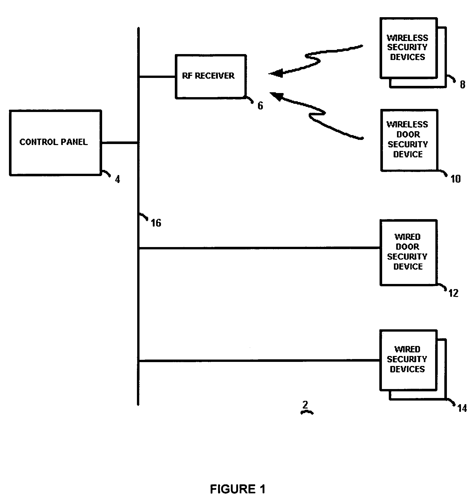
[0024]The preferred embodiment of the present invention will now be described with respect to the Figures. FIG. 1 illustrates a block diagram of a security system 2 having a control panel 4 connected by a security system bus 16 to one or more wired security devices 14 as well known in the art. Security devices 14 may include, for example, a passive infrared (PIR) sensor for sensing motion of a protected volume of space, a smoke or heat detector, a glass break sensor, and the like. In addition, an RF receiver 6 is connected to the control panel 4, and provides wireless communications with wireless security devices 8 as well known in the art. These wireless security devices may also be PIR sensors, glass break sensors, etc. The control panel 4 operates as known in the art (except as modified in accordance with the present invention to interoperate with the door security devices described herein), including processing of alarm signals from the various security devices, arming the syste...


PUM


Abstract

A lock position detection device includes a door locking mechanism, a magnetic field sensor such as a reed switch and a wireless transmitter. A magnet enters proximity of the sensor when the actuator is operated to one position and causes the sensor to output a first signal via the RF transmitter, and exits proximity of the sensor when the actuator is operated to another position and causes the sensor to output a second signal. A magnetic field shield is located with respect to the sensor to prevent a magnetic field from outside the door from being detected by the sensor. The magnet is coupled to the door locking mechanism such that the magnet enters and exits proximity of the sensor at an angle generally perpendicular to the sensor when the actuator is operated between positions, substantially along a line that is offset from a centerline of the reed switch.

Description

TECHNICAL FIELD[0001]This invention relates to security systems, and in particular to a security device that operates in conjunction with a lock or deadbolt on an entry door to selectively arm and / or disarm the security system in an automatic manner.BACKGROUND ART[0002]Alarm systems monitor sensors to determine the presence of people within a protected space. If the alarm system detects a breach of the protected space it will respond based on the state of the system. Possible system states include “disarmed”, “armed stay”, and “armed away.” If the system is disarmed it will not cause an alarm due to a breach of perimeter or interior sensors. If the system is armed stay, it will alarm due to a breach of the perimeter sensors, but not due to a breach the interior sensors. If the system is armed away it will alarm based on a breach of the perimeter or interior sensors. The state of the system is determined by the needs of the occupants of the premises. If all of the occupants are leavi...

Claims


Application Information

Patent Timeline
Patent Type & Authority Patents(United States)
IPC IPC(8): E05B45/06G08B13/08
CPCE05B45/06E05B2047/0069
Inventor LEE, ROBERT EESKILDSEN, KENNETH G
Owner HONEYWELL INT INC
Why Eureka
Try Eureka