
Precise location of buried metallic pipes and cables in the presence of signal distortion

a technology of metallic pipes and cables, applied in the field of detection of electromagnetic signals, can solve the problems of bias in the estimated centerline and it is difficult to determine whether the receiver is tracking the targeted conductor or whether the receiver is erroneously tracking a neighboring conductor, so as to accurately present the centerline and depth of the targeted conductor

Active Publication Date: 2008-04-08
BUSAN TRANSPORTATION CORPORATION
View PDF2 Cites 99 Cited by
  • Summary
  • Abstract
  • Description
  • Claims
  • Application Information

AI Technical Summary

Benefits of technology

[0012]In accordance with the present invention, a line locator system used in walkover locate mode is presented that can accurately present a precise centerline and depth of the targeted conductor even in the presence of high field distortion due to bleedover.

Problems solved by technology

In some cases, there may be bias in the targeted conductor's estimated centerline as a result of distortion due to bleedover.
In conventional receivers, it is very difficult to determine whether the receiver is tracking the targeted conductor or whether the receiver is erroneously tracking a neighboring conductor.

Method used


Image

  • Precise location of buried metallic pipes and cables in the presence of signal distortion
  • Precise location of buried metallic pipes and cables in the presence of signal distortion
  • Precise location of buried metallic pipes and cables in the presence of signal distortion

Examples


Embodiment Construction

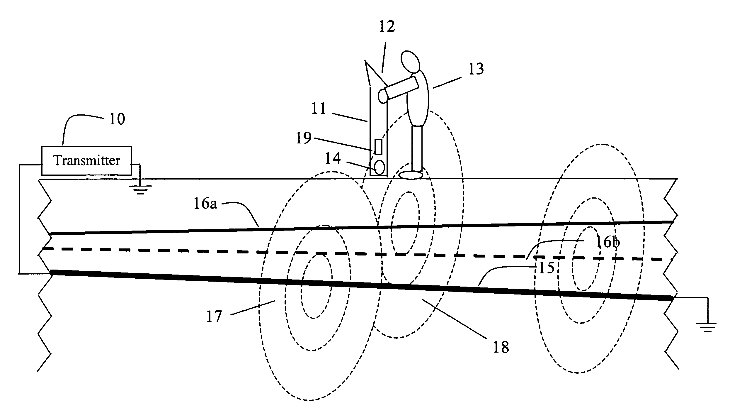
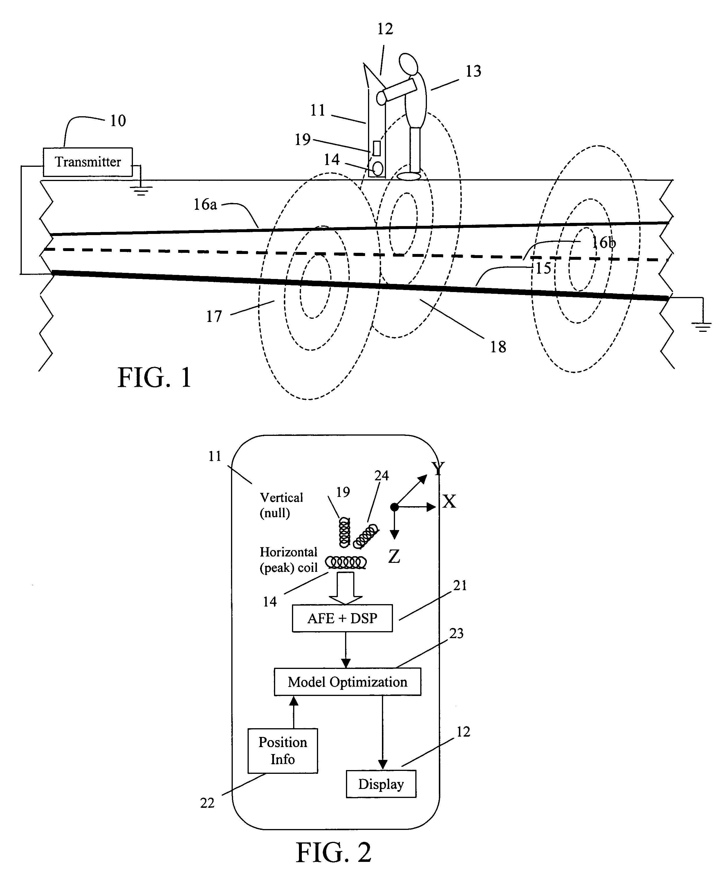
[0024]FIG. 1 illustrates a line location environment with a line locator 11. A target cable 15 energized by an electric current from transmitter 10 emits an electromagnetic field 17. Electromagnetic field 17 induces a current in nearby bleedover conductors such as conductors 16A and 16B (collectively conductors 16) because of resistive, inductive, or capacitive bleedover. The bleedover current in conductors 16 emits an electromagnetic field 18. The sum of the two fields can be detected at the surface by electromagnetic detector coils such as electromagnetic detector coils 14 and 19 of line locator 11. If locator 11 includes both vertical coil 19 and horizontal coil 14, two orthogonal sets of measurements of the strength of the electromagnetic field as a function of position over the target line can be obtained. Orthogonal horizontal coil 24 measures the magnetic field that does not lie in the plane defined by vertical coil 19 and horizontal coil 14. In general, line locator 11 may i...


PUM


Abstract

A new approach for locating an underground line described herein remains accurate in the face of bleedover by including both amplitude and phase from at least two magnetic field strength sensors in the measurement set. A numerical optimization step is introduced to deduce the positions and currents of each of several cables, of which one is the targeted cable and the others are termed bleedover cables. Furthermore, some embodiments of the method accounts for practical problems that exist in the field that relate to reliable estimation of cable positions, like the phase transfer function between transmitter and receiver, the estimation of confidence bounds for each estimate, and the rejection of false positive locates due to the presence of noise and interference.

Description

BACKGROUND[0001]1. Field of the Invention[0002]The present invention relates to detection of electromagnetic signals from targeted hidden conductors and, in particular, to the precise location of such conductors in the presence of signal distortion.[0003]2. Discussion of Related Art[0004]Underground pipe and cable locators (sometimes termed line locators) have existed for many years and are well known. Line locator systems typically include a mobile receiver and a transmitter. The transmitter can be coupled to a target conductor, either by direct electrical connection or through induction, to provide a current signal on the target conductor. The receiver detects and processes signals resulting from the electromagnetic field generated at the target conductor as a result of the current signal. The signal detected at the line locator can be a continuous wave sinusoidal signal provided to the target conductor by the transmitter.[0005]The transmitter is often physically separated from th...

Claims


Application Information

Patent Timeline
Patent Type & Authority Patents(United States)
IPC IPC(8): G01V3/15
CPCG01V3/081
Inventor GUDMUNDSSON, THORKELLWAITE, JIMOVERBY, JOHANPOLAK, STEVANLINDSTROM, NIKLAS
Owner BUSAN TRANSPORTATION CORPORATION
Learn More