Method and device for temperature monitoring along a measuring line

a technology of temperature monitoring and measuring line, which is applied in the direction of instruments, heat measurement, thermometers using value differences, etc., can solve the problems of changing the temperature threshold value, requiring a costly design of the sensor line, and reducing the maintenance cost in the case of leakage, so as to increase the cost effectiveness of the detection device, the effect of simple, fast and precise determination of the location

Active Publication Date: 2008-04-08
AIRBUS OPERATIONS GMBH
View PDF15 Cites 5 Cited by
  • Summary
  • Abstract
  • Description
  • Claims
  • Application Information

AI Technical Summary

Benefits of technology

[0006]This may allow a simple registering of a location along a measuring line, at which location a temperature change takes place.
[0007]Advantageously, this makes possible a simple, fast and precise determination of a location of a temperature change. For example, when used in an aircraft, such precision can be achieved that the location of a leakage can be narrowed down to a service flap of said aircraft so that the maintenance expenditure in the case of a leakage is reduced.
[0008]Furthermore, on the basis of the present invention, less complex and thus more economical types of cable can be used, and there is no need to use double-conductor cables with eutectic salts. This increases the cost effectiveness of the detecting device.
[0010]Advantageously, the detection of ohmic, capacitive or inductive changes in the measuring line may be detected as a result of excessive heat build-up, which in turn makes it possible to use various types of cables so that overheating-detection circuits can be implemented easily and economically. Furthermore, an alarm threshold value and the response characteristics of the detecting device can simply be set within a wide range by a corresponding selection of the cable type and by setting the evaluation circuit. Furthermore, by adaptive anti-distortion and processing in the image range or frequency range, very good measuring accuracy can be achieved which results in a reduction in the maintenance effort during troubleshooting. According to a preferred embodiment of the present invention, essentially all the components of the detecting device (except for the warning wires, i.e. the measuring lines) can be implemented in digital form. This results in a simple and economical detecting device.

Problems solved by technology

However, such a bridge-type measuring method, i.e. locating a leakage by way of a measuring bridge, requires an expensive design of the sensor line.
Since the length of the sensor lines, for example in a large passenger aircraft, can be substantial (up to 400 m), this leads to a considerable system weight and to considerable expenditure.
Moreover, such a twin-conductor cable with a centre conductor and sheath comprising thermally sensitive eutectic salt can only be used for a temperature threshold which corresponds to the material properties of the eutectic salt.
Changes in this temperature threshold value can only be made within very narrow limits and then require costly development, e.g. to develop a corresponding new salt.
Accordingly, with this known solution it is not possible to set the temperature threshold value without incurring substantial expenditure.

Method used


Image

  • Method and device for temperature monitoring along a measuring line
  • Method and device for temperature monitoring along a measuring line
  • Method and device for temperature monitoring along a measuring line

Examples


Embodiment Construction

[0012]Below, exemplary embodiments of the present invention are described with reference to the accompanying figures.

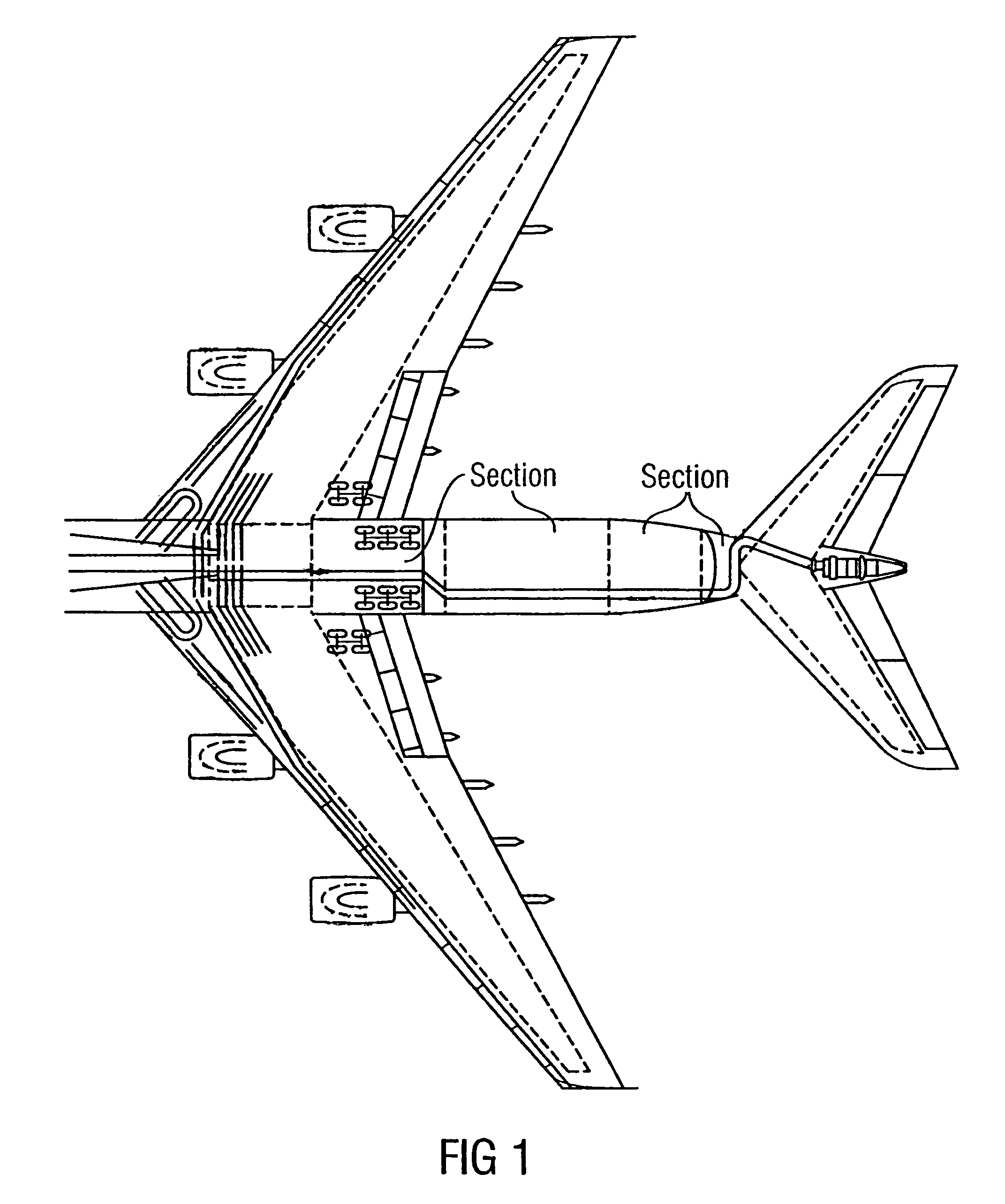
[0013]FIG. 1 shows an exemplary embodiment of the arrangement of measuring lines of the detecting device according to the present invention, as they can for example be arranged in an aircraft of the type Airbus A380.

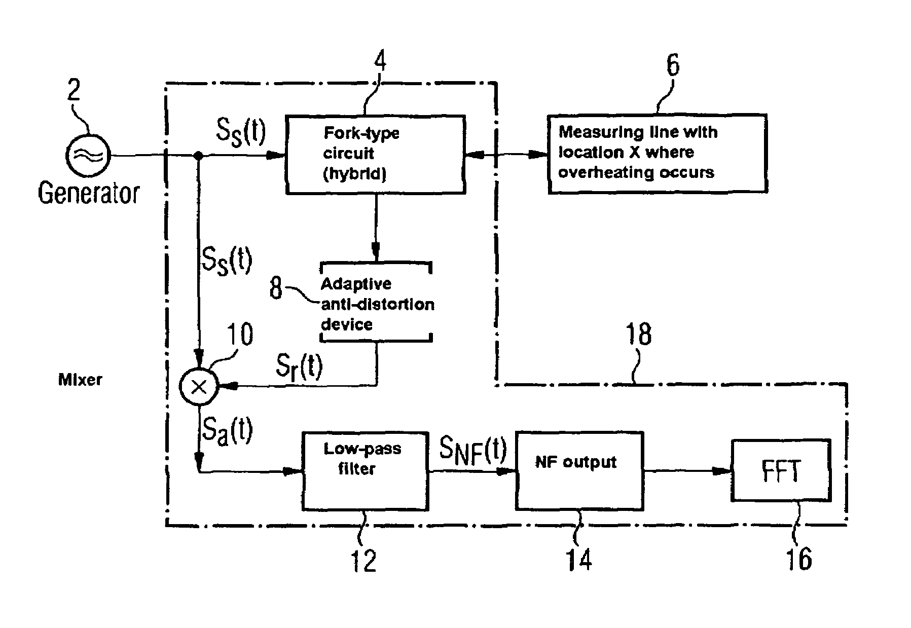
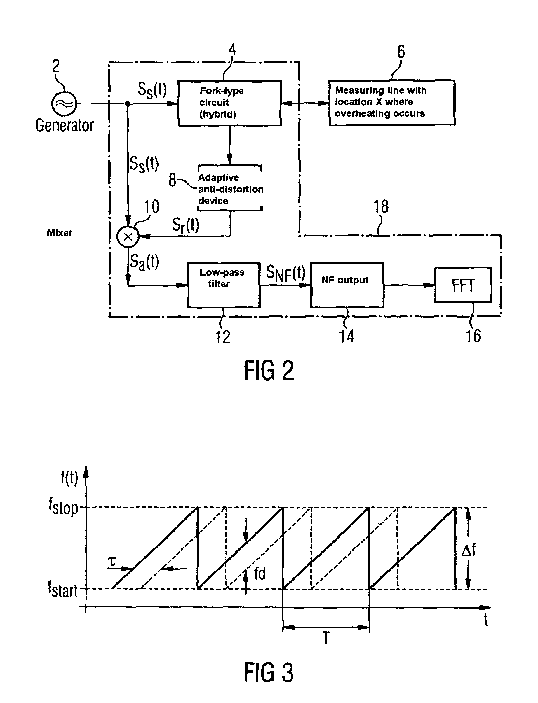
[0014]FIG. 2 shows a simplified block diagram of an exemplary embodiment of the detecting device according to the present invention.

[0015]FIG. 3 shows a time lapse diagram which depicts a frequency curve of the transmit signal and a frequency curve of the receive signal in the detecting device according to the present invention.

[0016]Below, with reference to FIGS. 1 to 3, an exemplary embodiment of the detecting device for detecting a location along a measuring line, at which location a temperature change takes place, is described with reference to a temperature monitoring device for hot-air supply pipes of an aircraft. However, it must be pointed out that...


PUM

PropertyMeasurementUnit
lengthaaaaaaaaaa
temperatureaaaaaaaaaa
frequencyaaaaaaaaaa

Abstract

The present invention relates to a registering device for registering a location along a measuring line, at which location a temperature change takes place. In an advantageous way, according to one exemplary embodiment of the present invention, by means of the FMCW method a location on the measuring line is determined, at which location a temperature increase exceeds a predefined threshold value. The location is determined on the basis of a signal which is registered by the measuring line in response to a fed-in frequency modulated signal from evaluation electronics. Advantageously, in this way a simple and lightweight overheating warning system is provided, for example for hot-air supply pipes in aircraft.

Description

TECHNOLOGICAL BACKGROUND[0001]Modern transport aircraft generally use hot bleed air from the engines, among other things for airconditioning the cabin. To this effect, hot-air supply pipes lead from the engines to the cabin. These hot-air supply pipes comprise warning wires for the detection of any leakages. Usually this sensor line is a coaxial cable with a centre conductor and a sheath containing thermally sensitive eutectic salt as an insulation material. If at any point along the length of the measuring wire strong heating occurs as a result of a leakage, the resistance of the eutectic salt within the heated section drops and ensures that current starts to flow between the outer sheath and the centre conductor. This short circuit is then measured by way of a control unit. Nowadays a bridge-type measuring method is commonly used for precisely locating the leakage and for improving the servicability of the system.[0002]However, such a bridge-type measuring method, i.e. locating a ...

Claims


Application Information

Patent Timeline
Patent Type & Authority Patents(United States)
IPC IPC(8): G01K7/00G01K3/14
CPCG01K3/14
Inventor SCHAUMANN, OLIVERGROENNING, WILHELMSCHULDT, MARTIN
Owner AIRBUS OPERATIONS GMBH
Why Eureka
Try Eureka