Fluorescent or luminescent optical symbol scanner

a scanner and fluorescent light technology, applied in the field of optical scanning devices, can solve the problems of inability to carry an operator, inability to read bar codes in warehouses, shipping docks or receiving docks, and the scanner system is bulky and non-portable, and achieves the effect of convenient adapting to wireless battery-powered operation

Inactive Publication Date: 2008-04-15
INDAL DATA ENTRY AUTOMATION SYST
View PDF7 Cites 79 Cited by
  • Summary
  • Abstract
  • Description
  • Claims
  • Application Information

AI Technical Summary

Benefits of technology

[0008]It is another object to provide a hand-held scanner that is safe and convenient to use for reading invisibly printed fluorescent optical symbols.
[0009]It is a further object to provide a hand-held scanner and illuminator that permits a user to read and accurately decode a fluorescent or luminescent symbol that has been directly printed on an article and which scanner employs one or more low-power far-blue, UV / blue, UV or similar black-light source, or, in some cases, a visible light source, contained within an illuminator portion of the hand-held scanner.
[0013]According to one aspect of this invention, a scanner assembly is configured for detecting and decoding a small scale two dimensional optical symbol, such as a 2-D bar code symbol, lying on a surface of an article. The scanner or optics assembly can be based on, or incorporated into a portable (hand-held) contact device, and can be easily adapted for wireless battery-powered operation.

Problems solved by technology

These scanner systems are bulky and non-portable, so they cannot be carried by an operator.
This makes it impossible to read the bar codes in a warehouse, shipping dock or receiving dock environment where the workers could be provided with hand-held scanners.
In addition, because of the rather harmful effects from ultraviolet radiation, conventional black light sources typically have to be shielded to protect the workers from exposure to skin or eyes.
Consequently, invisibly printed phosphorescent bar code symbols can only be read under special circumstances, as the bulk, weight, and complexity of the reader equipment has limited their widespread usage.
No one previously had considered using black-light emitting diodes in connection with any sort of hand-held scanner device to permit their use in reading “invisible” luminescent or fluorescent optical symbols, such as bar codes.
That patent does not discuss any safety issues, and does not attempt to eliminate or minimize the effects of stray UV illumination.
However, prior hand held scanners are unable to discern bar coded symbols formed of these fluorescent inks, because of the low contrast between the target and background.

Method used


Image

  • Fluorescent or luminescent optical symbol scanner
  • Fluorescent or luminescent optical symbol scanner
  • Fluorescent or luminescent optical symbol scanner

Examples


Embodiment Construction

)

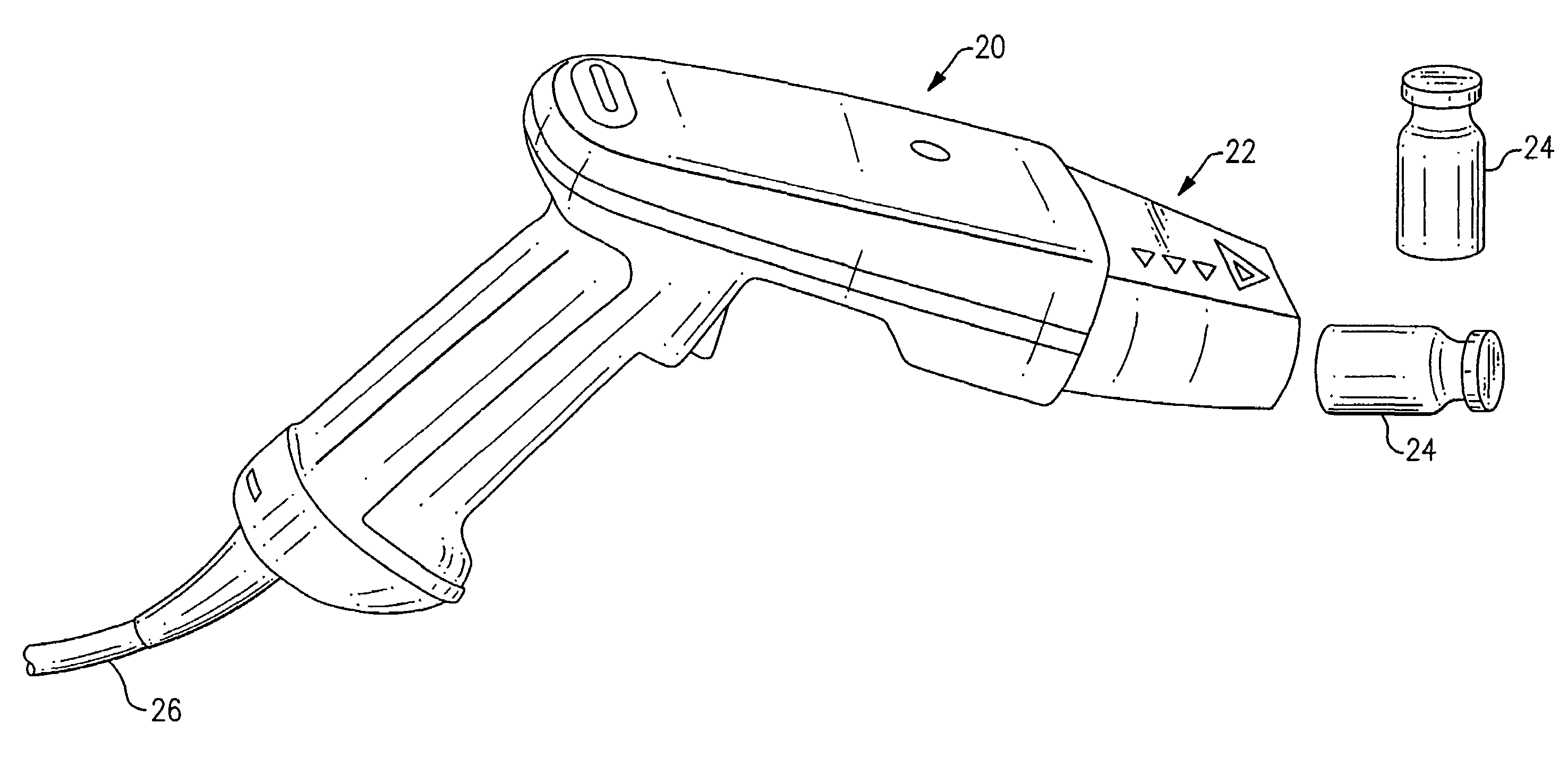
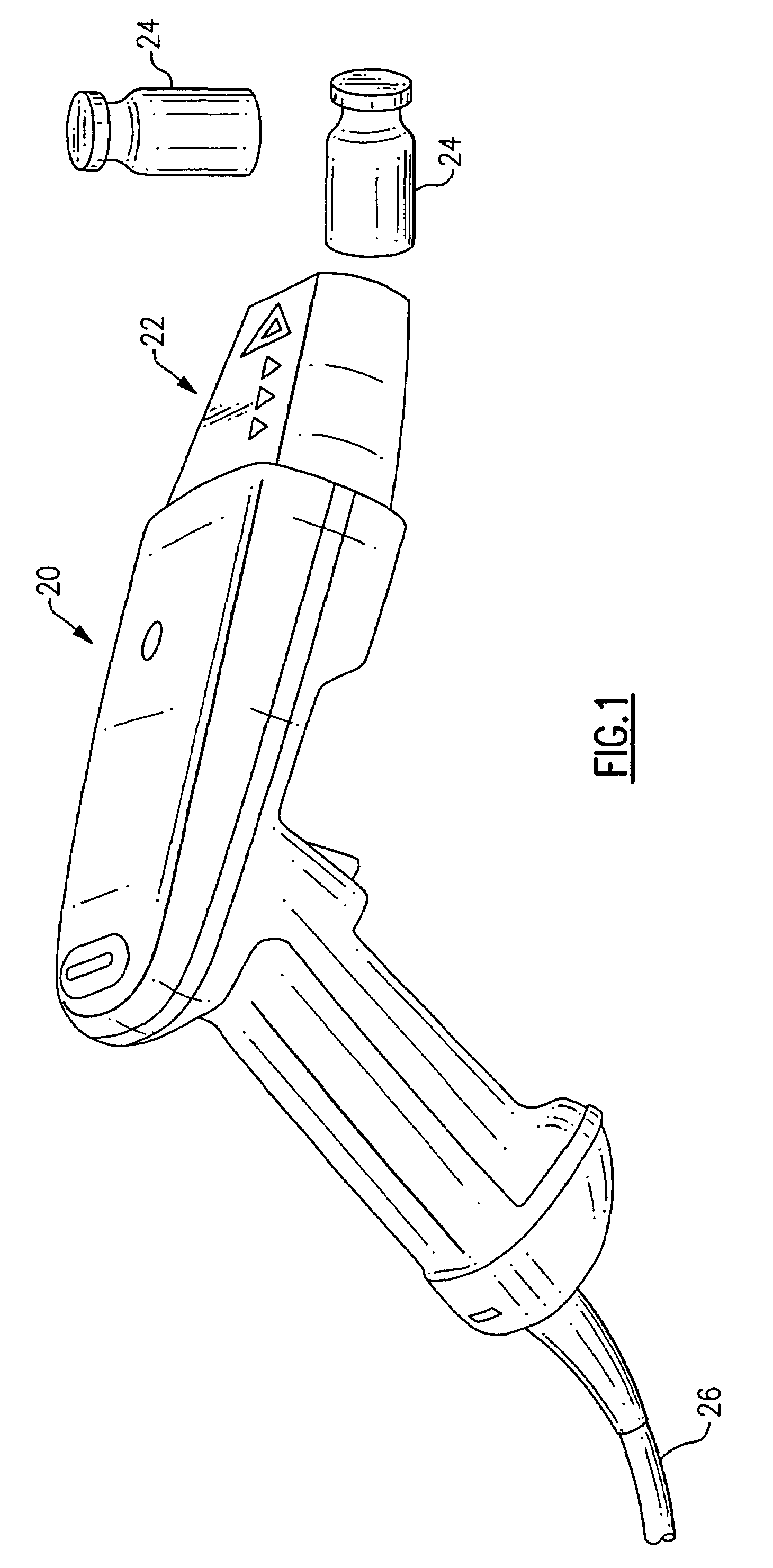
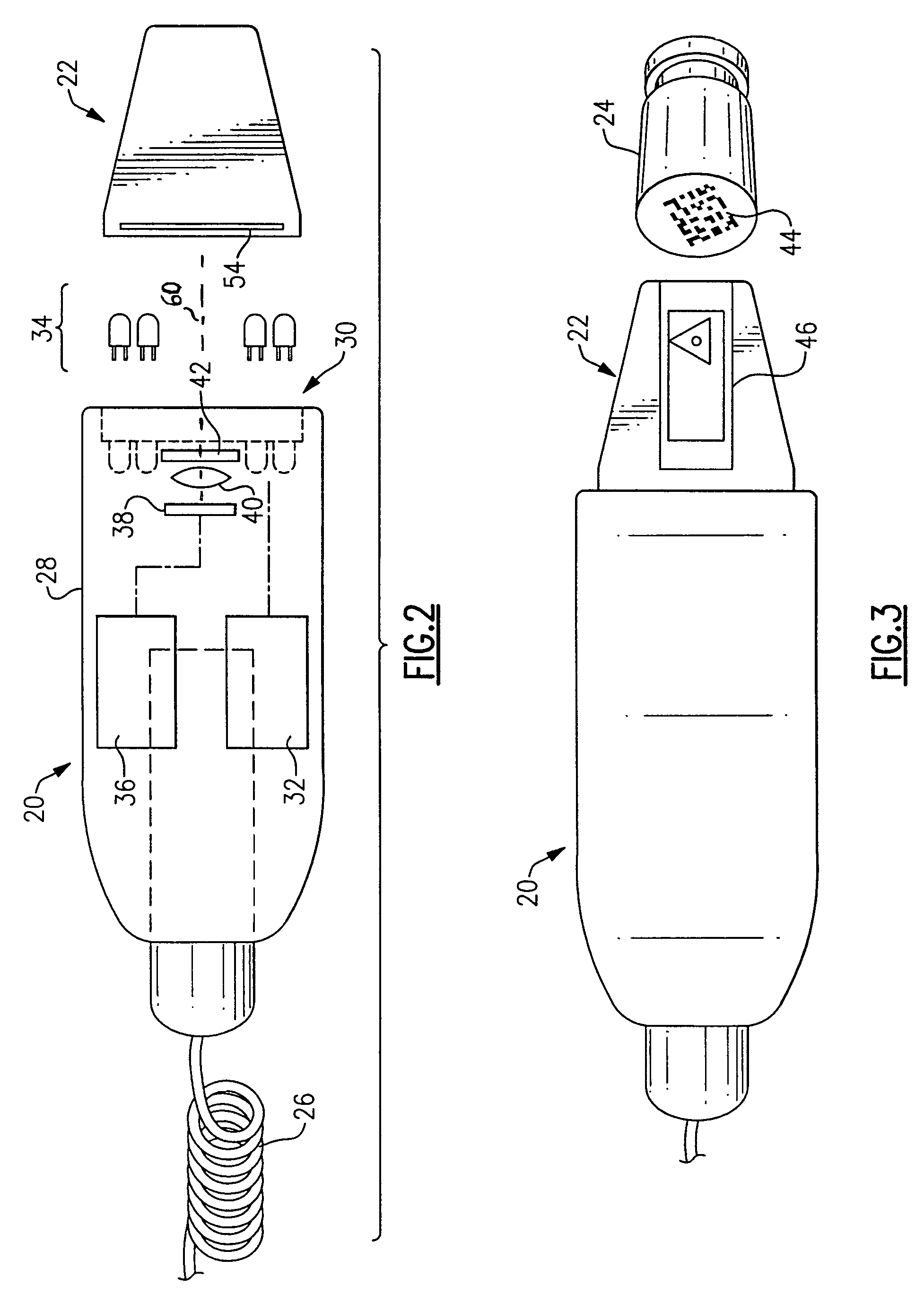
[0035]With reference to the Drawing, and initially to FIG. 1, a hand-held data inputting scanner 20, i.e., a hand-held two dimensional bar code scanner, includes an illumination attachment which incorporates a nosepiece 22, with the nosepiece being mounted on the front or distal end of the body of the scanner 20. This scanner employs black-light illumination and is designed to read a bar code symbol that is invisibly printed on a surface, here on the base of a vial 24 of the type used for containing medication. The bar code symbol may be linear, 2-D or 3-D, and is intended here to identify the contents of the vial 24, including the type of pharmaceutical, place of manufacture, date, and batch number, plus other required information. This information is initially used for automated processing in factory, and is typically read in an automated device in which black light, i.e., ultraviolet, is provided from a discharge tube to illuminate the bottoms of the vials as they pass by on a p...


PUM


Abstract

A hand-held, compact fixed mounted or mobile optical symbol scanner assembly that employs black-light emitting diodes to illuminate luminescent or fluorescent bar code symbols that are invisibly printed or formed the surface of an article. The scanner employs an array of far blue or UV LEDs or laser diodes. An optional nosepiece or shroud on the distal face of the scanner device limits glare from ambient light and also protects against stray UV light. A filter disposed in advance of the imager device blocks the illuminating wavelength but transmits the luminescent light from the target. With proper selection of optical filters and illumination LED wavelengths, the scanner can be used with inks or dyes that fluoresce when exposed to light in the visible spectrum.

Description

BACKGROUND OF THE INVENTION[0001]This invention is directed to optical scanning devices, such as bar code scanners, and is more particularly concerned with an arrangement for reading optical symbols, e.g., small linear or two-dimensional bar code symbols that are directly marked on articles. The invention is more particularly concerned with a combination of a hand-held optical scanner and an illuminator that provides stimulating illumination onto a bar code symbol or other symbol which is formed of a fluorescent or phosphorescent or luminescent material. This scanner may be of a corded or cordless variety or built into a data terminal or be of a compact, fixed mount style.[0002]Within the past several years, two-dimensional bar code systems have begun to be employed on small articles so that the article can be tracked throughout manufacturing, packaging, and shipping. In some cases, luminescent or fluorescent bar code symbols are invisibly printed onto articles, e.g., onto the base ...

Claims


Application Information

Patent Timeline
Patent Type & Authority Patents(United States)
IPC IPC(8): G06K7/10
CPCG06K7/10G06K7/10722G06K19/0614G06K7/10881G06K7/12G06K7/10732
Inventor HATTERSLEY, JOHN R.BLACKWELL, III, FRANCIS O.
Owner INDAL DATA ENTRY AUTOMATION SYST
Why Eureka
Try Eureka