Bumper for a motor vehicle

a technology for bumpers and motor vehicles, applied in the direction of vehicle bodies, roofs, monocoque constructions, etc., can solve the problems of limited access to the crash box end, difficult welding of the end of the crash box to the cross member about the entire circumference of the crash box, and heavy construction. , to achieve the effect of positively affecting the stiffness property of the crash box

Active Publication Date: 2008-04-15
BENTELER AUTOMOBILTECHNIK GMBH
View PDF19 Cites 81 Cited by
  • Summary
  • Abstract
  • Description
  • Claims
  • Application Information

AI Technical Summary

Benefits of technology

[0012]The present invention resolves prior art problems by providing a bumper in which the wall of the cross member is formed with at least one depression to project into the open end of the crash box, whereby the vertical legs of the crash box are joined to the wall of the cross member while the horizontal legs of the crash box are distanced from the wall. As a result, the vertical legs are secured to the cross member in a stable manner, and the movement behavior of the horizontal legs becomes predictable in longitudinal direction of the crash box by virtue of its disposition in the depression. Thus, deformation of the crash box is controlled and thus foreseeable, as the vertical legs of the crash box to the left and right of the depression are joined to the wall of the cross member, although the horizontal legs remain shy of the wall. The depression is located within the crash box and distanced from the horizontal legs. In the event of an impact, the depression in the wall of the cross member deforms to rest against the crash box. The free space to the horizontal legs assists hereby the controlled deformation, in particular as the crash box crumples. The distance between the horizontal legs of the crash box to the wall of the cross member ensures a desired initial folding, thereby positively affecting the yielding behavior of the bumper in the event of a crash and providing superior protection of the vehicle body overall. In view of the improved predictability of the deformation behavior of the bumper during simulation, a manufacturer is able to develop bumper systems that are superior in quality and reliable in operation and can be best suited to the overall vehicle system. In particular, undefined deformation behavior of the cross member proximal end of the crash box during initial moment of an impact as a result of indefinable conditions, such as direction of impact and speed or friction conditions, can be significantly reduced.
[0014]The depression in the cross member, projecting out toward the crash boxes into the cross member proximal ends may be constructed in many ways. While the depression may have a trough-shaped or bulbed configuration, implemented through stamping, or may have a channel configuration in the form of an embossment, other configurations are, of course, possible so long as a targeted orientation of the degrees of freedom of the crash box in the event of an impact and thus an undefined escape of the horizontal legs is prevented.
[0016]According to another feature of the present invention, the wall of the cross member may be formed in addition to the presence of a depression or depressions, with an opening in the area of the end surface of the crash box. In this way, it is possible to bring in a tow lug for a lug attachment inside the crash box.
[0017]According to another feature of the present invention, the crash box is defined by a length axis and may be formed with embossments and stamped zones extending transversely to the length axis. The provision of embossments or stamped zones assists a targeted deformation of the crash box. In addition, the stiffness property of a crash box can be positively affected by suitably selecting the type, configuration and disposition of the embossments or stamped zones.

Problems solved by technology

This construction is heavy and complicated.
Welding the end of a crash box to the cross member about the entire circumference of the crash box is difficult to implement in view of the limited accessibility to the crash box end.
This, however, adversely affects deformation of the crash box.
Practice has shown that the behavior of the crash box in the contact area of the non-welded upper and lower horizontal legs of the crash box is unpredictable so that a reliable assessment of the crumpling behavior of the bumper has been impossible to foresee in the event of an impact.

Method used


Image

  • Bumper for a motor vehicle
  • Bumper for a motor vehicle
  • Bumper for a motor vehicle

Examples


first embodiment

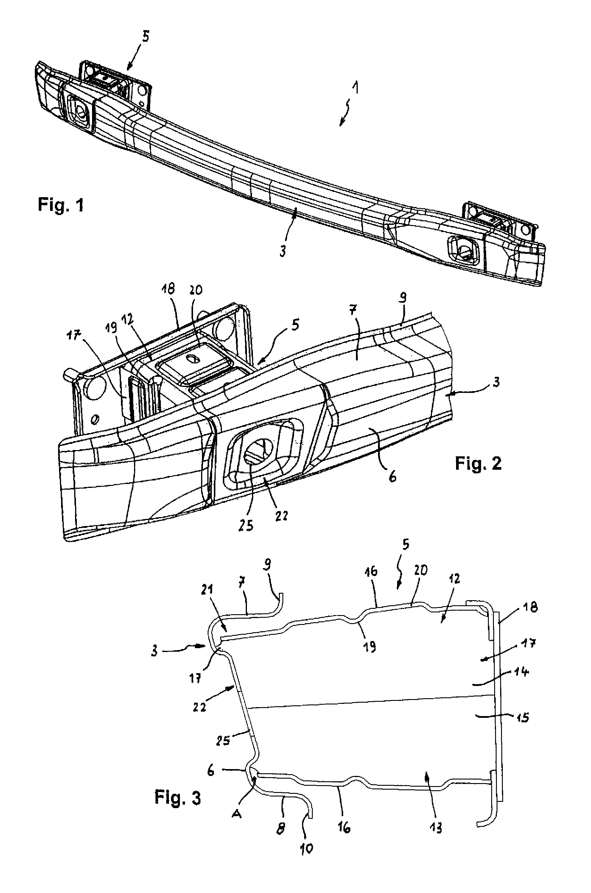
[0031]Turning now to the drawing, and in particular to FIG. 1, there is shown a perspective illustration of a bumper according to the present invention, generally designated by reference numeral 1, for a motor vehicle. The bumper 1 includes a cross member 3 which extends transversely to unillustrated side rails of the vehicle frame (not shown). Disposed integrally between the side rails and the cross member 3 are casing-like crash boxes 5 to form deformation elements for absorbing energy in the event of a crash.

[0032]As shown in particular in FIGS. 2 and 3, the cross member 3 has, at least over a major part of its length dimension, an open profile of U-shaped cross section toward the crash boxes 5. The cross member 3 has a front wall 6, an upper leg 7 and a lower leg 8, whereby the upper and lower legs 7, 8 extend from the wall 6, as shown in particular in FIG. 3, and terminate in outwardly directed flanges 9, 19, respectively.

[0033]Each crash box 5 is constructed as a deformation m...

second embodiment

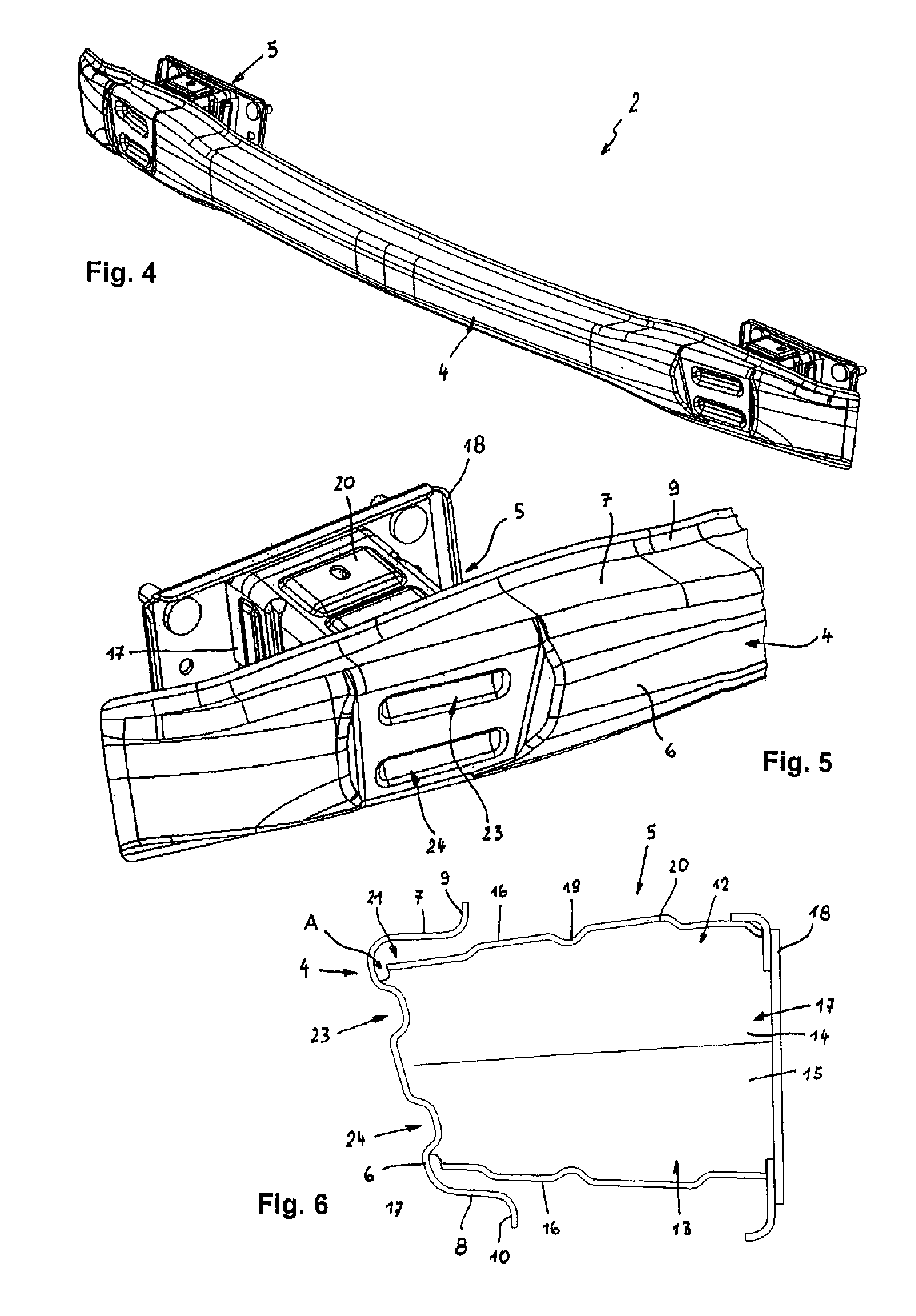
[0037]Referring now to FIG. 4, there is shown a perspective illustration of a bumper according to the present invention, generally designated by reference numeral 2. Parts corresponding with those in FIG. 1 are denoted by identical reference numerals and not explained again. The description below will center on the differences between the embodiments. In this embodiment, the bumper 2 has a cross member 4 which differs from the cross member 3 of bumper 1 by providing the wall 6 of the cross member 4 with two depressions 23, 24 which have a channel-like configuration in the form of embossments, as shown in FIGS. 5 and 6. Both depressions 23, 24 are disposed above one another at a vertical distance and extend in parallel relationship to the upper and lower legs 7, 8 of the cross member 4. The depressions 23, 24 are hereby situated in proximity of the upper and lower horizontal legs 17, respectively, of the crash box 5.


PUM


Abstract

A bumper for a motor vehicle includes a cross member disposed transversely to side rails of a motor vehicle frame and having a U-shaped cross section with a wall and two legs extending from opposite ends of the wall. The cross member is supported via integral crash boxes against the side rails. Each crash box has a cross member proximal end which abuts against the wall of the cross member, and includes vertical legs and horizontal legs to define a casing-like configuration. The wall of the cross member is formed in an area of the cross member proximal end of the crash box with a depression which extends in a direction of the crash box, with the vertical legs of the crash box joined at the cross member proximal end to the wall of the cross member, and with the horizontal legs of the crash box spaced from the wall of the cross member by a distance.

Description

CROSS-REFERENCES TO RELATED APPLICATIONS[0001]This application claims the priority of German Patent Application, Serial No. 10 2005 029 770.6, filed Jun. 24, 2005, pursuant to 35 U.S.C. 119(a)-(d), the content of which is incorporated herein by reference.BACKGROUND OF THE INVENTION[0002]The present invention relates, in general, to a bumper for a motor vehicle.[0003]Nothing in the following discussion of the state of the art is to be construed as an admission of prior art.[0004]Bumpers are typically arranged across the front and rear of a motor vehicle between the plastic shell of the vehicle body and the frame of the motor vehicle. To prevent damage to the vehicle body structure in the event of a crash or impact at low speed, crash boxes are integrated to absorb energy caused by the impact and to convert the energy in deformation work.[0005]German Offenlegungsschrift DE 42 38 631 A1 discloses a shock absorption device for absorbing the impact energy between a bumper and a vehicle b...

Claims


Application Information

Patent Timeline
Patent Type & Authority Patents(United States)
IPC IPC(8): B60R19/34
CPCB60R19/18B60R19/34B60R2019/1826
Inventor ROLL, MICHAELLUTKE-BEXTEN, ULRICHARNS, WILHELMMOLLEMEIER, ELMAR
Owner BENTELER AUTOMOBILTECHNIK GMBH
Why Eureka
Try Eureka