Deployment system for thermal radiating materials

a technology of thermal radiation and deployment system, which is applied in the direction of process and machine control, and instruments, can solve the problems of increasing the wear and tear of the mat system, requiring expensive repair of the thermal element, and the failure of the embedded coil or element, so as to reduce the input energy and improve the reliability. the effect of reliability

Inactive Publication Date: 2008-04-15
HOFFMAN WILLIAM H +1
View PDF29 Cites 3 Cited by
  • Summary
  • Abstract
  • Description
  • Claims
  • Application Information

AI Technical Summary

Benefits of technology

[0012]The invention is designed as such, to enhance the human productivity and ease human interaction in deployment of the prior art thermal radiating or generating devices for the removal or destruction of snow and ice in a special and unique way. The deployment system as disclosed and claimed can be designed to operate autonomously with automatic controls and sensors to control both the thermal system and the technology of controlling a deployment system as defined by my invention. The invention is well suited to autonomously deploy and retract rolled membranes and or flexible materials out over a flat or gently sloped surface area. The inherent flexibility of the mat allows it to traverse gently curved surfaces. This invention improves upon the deployment and storage of the multitude of snow melting devices available in the market. The invention as disclosed allows for easy deployment and storage in a wide range of applications. It is generally understood in the prior art, that the easy placement of a heating element, mat, tile, sheet is desirable. This invention relieves the human being from having to strenuously participate in the deployment and storage of this material. It is therefore an object of this invention to provide an autonomous deployment system for flexible thermal radiating materials that is easy for a human to use and requires minimal manual efforts.
[0016]It is another object of said track and driver system that it be self-clearing or cleaning to improve its reliability.
[0017]It is another object of the invention that the deployment system use an equal or balanced tension deployment to reduce the input energy required to deploy said system.
[0019]It is another object of the invention that the deployment system use a bi-relational drive system to further reduce the input energy required to deploy said system.
[0021]It is another object of the invention that the deployment system use a bi-relational drive system to further reduce the input energy required to deploy said system.
[0022]It is another object of the invention that the deployment system use a bi-directional torque applier drive system to improve the reliability and further reduce the input energy required to deploy said system.

Problems solved by technology

Other mat systems allow for people to walk on them when in use although this clearly subjects the mat systems to increased wear and tear and other environmental stresses.
For example, if the surface material cracks from normal seasonal variations or use, the embedded coils or element may also break requiring expensive repairs to the thermal elements for repair.
To date nothing has been designed and or patented in the deployment and storage of these mat designs that does not require the intervention of great amounts of human manpower to deploy and store these devices.
Manual deployment may be very difficult for most people but is especially difficult for the aged, weak and sickly.
Additionally, the aesthetics of these unsightly mats lain across sidewalks and driveways can be an eye sore and a trip hazard.
Manually deployed mat styles found in the prior art have numerous limitations in deployment, such as in remote areas to which it is hard to get delivery personnel and equipment.

Method used


Image

  • Deployment system for thermal radiating materials
  • Deployment system for thermal radiating materials
  • Deployment system for thermal radiating materials

Examples


Embodiment Construction

—ELEMENT LISTING

[0063]

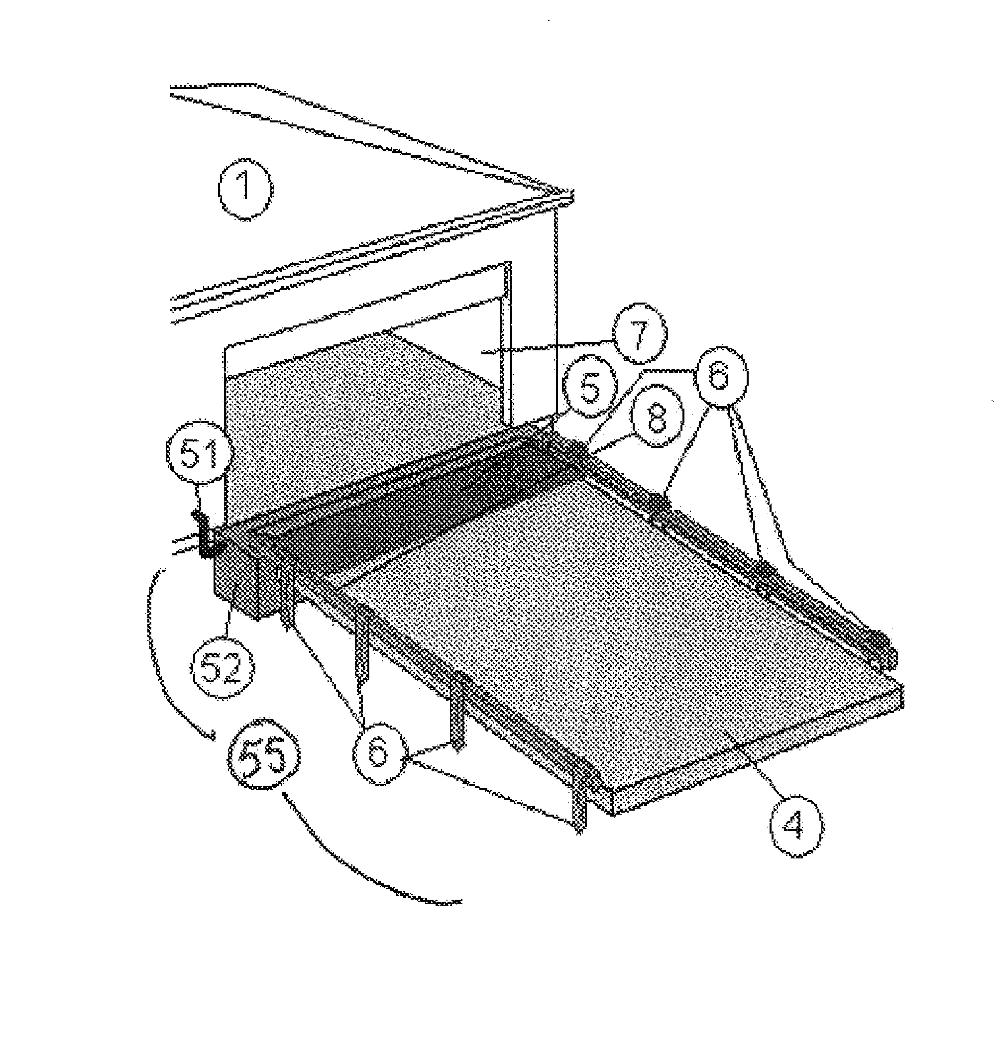
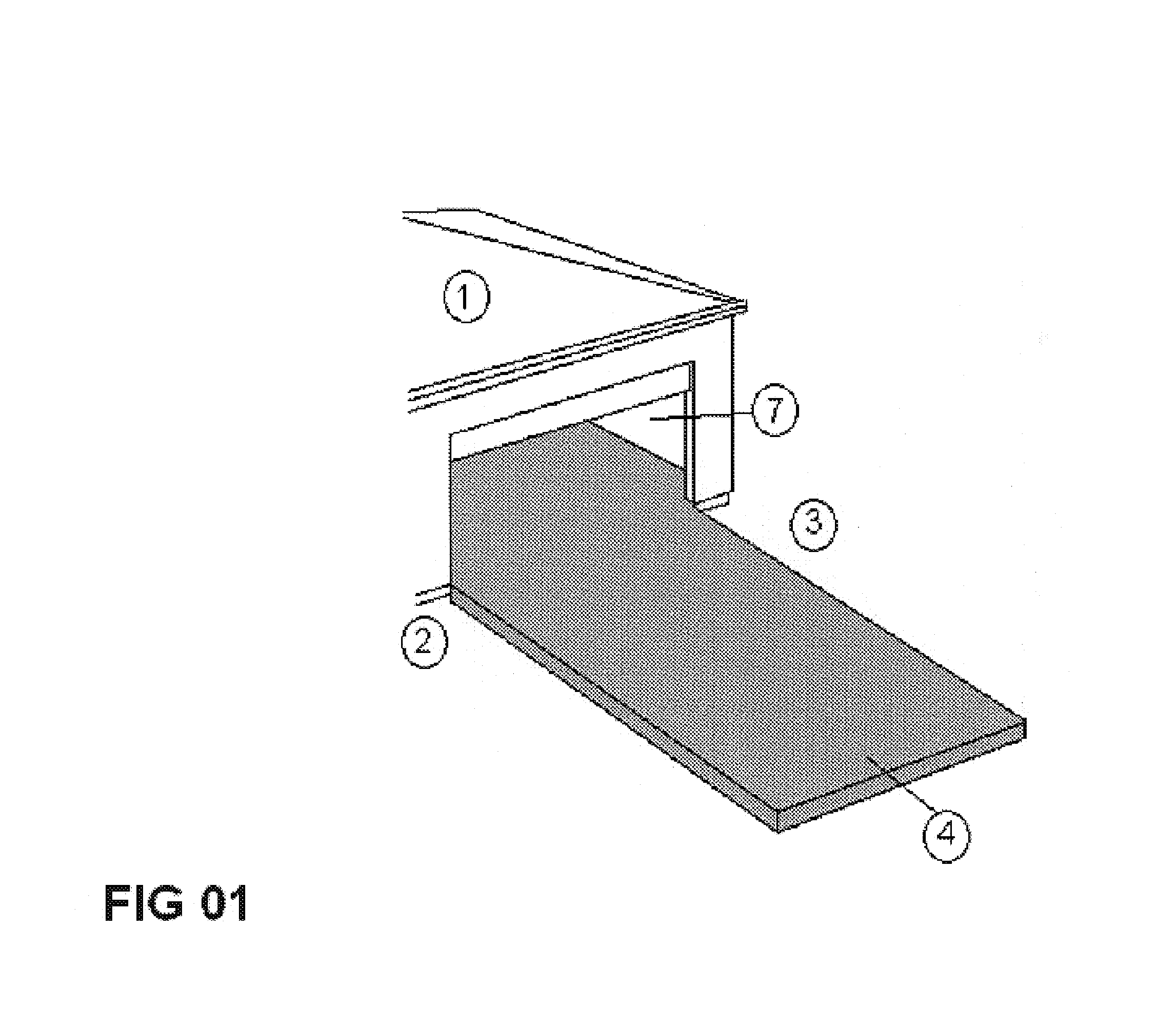
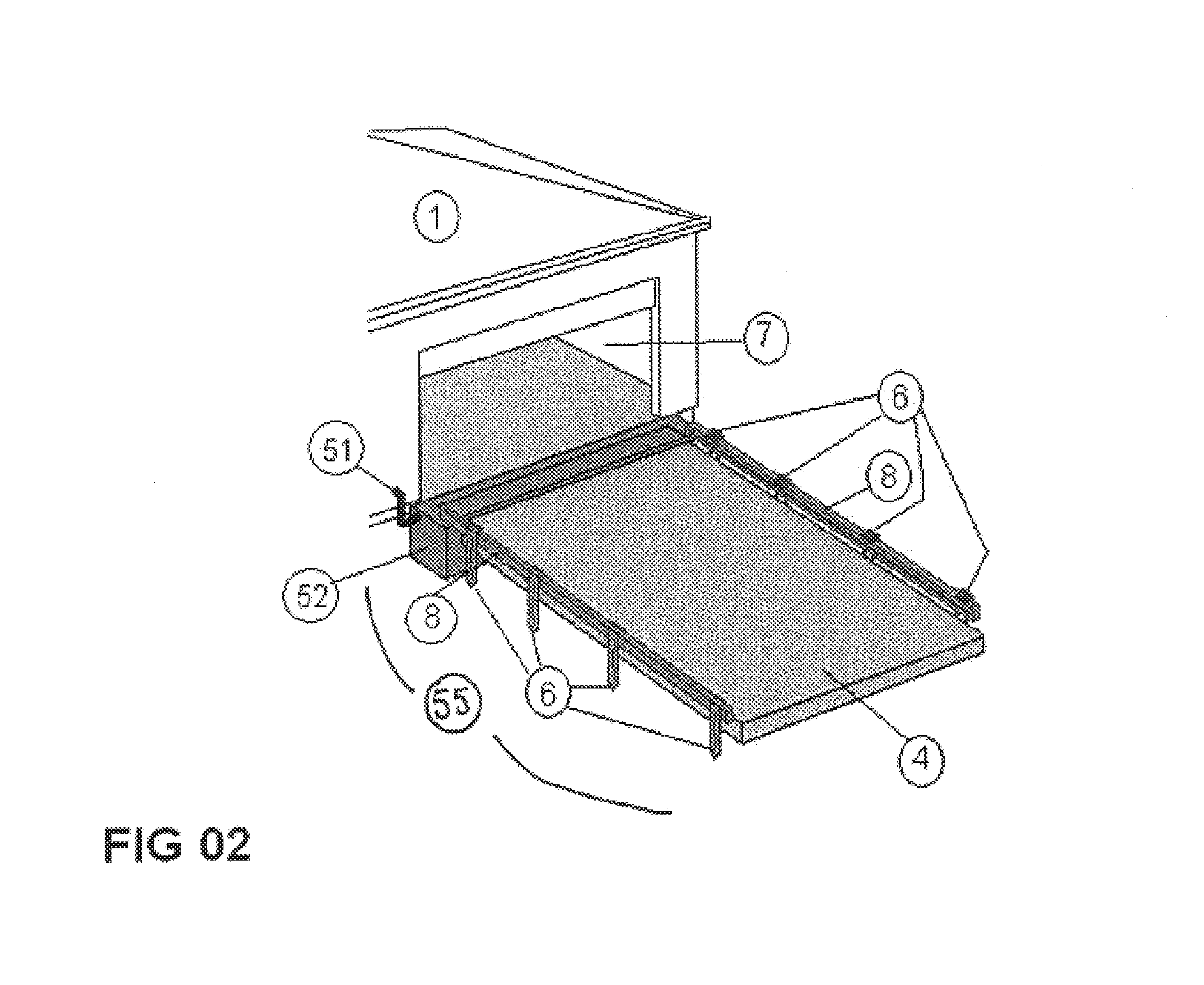
Listing of ElementsElement #Building or structure 1Support surface 2Deployment unit power source 3Driveway surface area 4Flexible thermal mat (material) 5Anchoring spike 6Open bay 7Track and rail assembly 8Thermal mat 5 one-half deployed 9Thermal mat 5 three-quarters10deployedThermal mat 5 fully deployed11Track & rail assembly end cap12Idler block assembly13Drive cable14Idler15External sensor collection pod16Cable guide tube17Drive shaft bushing18Environment sensor19Thermal mat roller axle20Thermal mat roller axle21Cable drive clamping tube22assemblyCompression screws23Cable tube guide24Clamping tube assembly beveled25surfacesProgrammable logic controller26Thermal mat anchoring point27Thermal mat drive axle bushing28and axle mounting slotThermal mat spool axle bushing29and axle mounting slotDeployment system housing30Housing re-enforcement rib or31supportThreaded adjusting bolt32Idler plate tongue33Drive cable idler stop foot34Adjusting bolt lock nut35Deploymen...


PUM


Abstract

An autonomous deployment system is herein for functional utilization in the physical placement and deployment of a heating or thermal mat(s). The system is designed to enhance human productivity and ease deployment of the prior art thermal radiating or generating devices for the removal and or inhibition of accumulation of snow and ice. The deployment system as can be designed to operate autonomously with automatic controls and sensors to control both the thermal system and the technology of controlling a deployment system. The system is well suited to autonomously deploy and retract rolled membranes and or flexible materials out over a flat or sloped surface area. The inherent flexibility of the mat allows it to traverse gently curved surfaces.

Description

CROSS REFERENCE TO RELATED APPLICATIONS[0001]Applicant herein claims priority from and incorporates herein by reference in its entirety provisional patent application filed on Dec. 22, 2004 and assigned Ser. No. 60,638,662.FIELD OF THE INVENTION[0002]This invention relates to a deployment apparatus and system used for melting snow using thermal radiating flexible mat-type systems. Elements disclosed and claimed also include a novel deployment system as well as the storage of the thermal radiating systems.STATEMENT REGARDING FEDERALLY SPONSORED RESEARCH OR DEVELOPMENT[0003]No federal funds were used to develop or create the invention disclosed and described in the patent application.REFERENCE TO SEQUENCE LISTING, A TABLE, OR A COMPUTER PROGRAM LISTING COMPACT DISK APPENDIX[0004]Not ApplicableBACKGROUND OF THE INVENTION[0005]The prior art describes a multitude of thermal mat designs, construction and features such as type of heating systems (dry or wet) applied, multiple materials for...

Claims


Application Information

Patent Timeline
Patent Type & Authority Patents(United States)
IPC IPC(8): H05B1/00
CPCE01C11/265
Inventor HOFFMAN, WILLIAM H.RUHL, SANDRA R.
Owner HOFFMAN WILLIAM H
Why Eureka
Try Eureka