Illuminating apparatus, image display apparatus, and projector

a technology of illumination apparatus and image display, which is applied in the direction of picture reproducers using projection devices, television systems, instruments, etc., can solve the problems of large illumination optical system, difficult to effectively use all the light flux from the light source, and large size of the illumination optical system

Inactive Publication Date: 2008-04-22
SEIKO EPSON CORP
View PDF32 Cites 40 Cited by
  • Summary
  • Abstract
  • Description
  • Claims
  • Application Information

AI Technical Summary

Problems solved by technology

However, because an angle that the spatial light modulator can cover is limited, it is difficult to effectively use the light flux from the light source.
Therefore, even if an LED array is employed in a projector to increase the light intensity, it is difficult to effectively use all the light flux from the light source because the etendue is preserved.
With this type of configuration, because the white light is separated into three colors by the color filters for each of the colors, an illumination optical system grows in size, and it is difficult to obtain a bright image with an even intensity distribution.
As described above, the conventional technology has problems of supplying an illumination light with a high brightness and a high usability and obtaining a bright image with an even intensity distribution.

Method used


Image

  • Illuminating apparatus, image display apparatus, and projector
  • Illuminating apparatus, image display apparatus, and projector
  • Illuminating apparatus, image display apparatus, and projector

Examples


first embodiment

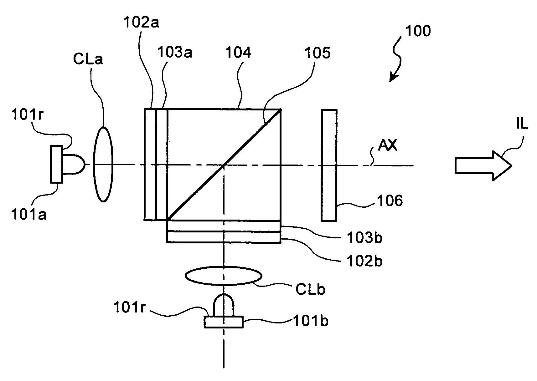
[0027]FIG. 1 is a schematic diagram of an illuminating apparatus according to the present invention. The illuminating apparatus 100 includes a first LED 101a that is a first solid light-emitting element and a second LED 101b that is a second solid light-emitting element. Both the first LED 101a and the second LED 101b emit light of same wavelength region, for example, a G-light. The G-light from the first LED 101a is incident on a collimating lens CLa. The collimating lens CLa converts the incident light into a substantially parallel light. The substantially parallel light is incident on a polarizing beam splitter 104 that is a polarized-light combining unit. On a side of the polarizing beam splitter 104 toward the first LED 101a, a λ / 4 waveplate 102a and a first reflection type polarizing plate 103a are bonded by an optically transparent adhesive.

[0028]The first reflection type polarizing plate 103a transmits a polarized light of one of a first oscillation direction and a second os...

fourth embodiment

[0056]FIG. 7 is a schematic diagram of a projector 700 according to the present invention. A first solid light-emitting element, a first LED 701a, and a second solid light-emitting element, a second LED 701b, provides a white light. The white light mentioned here includes both light of a wavelength region where a spectral distribution of the light is continuously broad and light having discrete peak wavelengths for the R-light, the G-light, and the B-light, respectively. The first LED 701a and the second LED 701b have a same configuration, so that the first LED 701a is explained as an example. Light emitted from the first LED 701a is reflected by a reflector 702a to a polarizing beam splitter 704. A focusing lens 703a having a positive refracting power focuses the light directly from the first LED 701a and the light reflected at the reflector 702a at an aperture 708. With this arrangement, the light from the first LED 701a is incident on a predetermined surface of the polarizing bea...


PUM


Abstract

An illuminating apparatus includes at least two solid light-emitting elements including a first solid light-emitting element and a second solid light-emitting element; a polarized-light combining unit that combines a first polarized light of a first oscillation direction and a second polarized light of a second oscillation direction substantially perpendicular to the second oscillating direction to guide the first polarized light and the second polarized light to an illumination direction by transmitting or reflecting the first polarized light and reflecting or transmitting the second polarized light; and a phase modulating element that converts a polarized light from the polarized-light combining unit into either of the first polarized light and the second polarized light.

Description

CROSS-REFERENCE TO RELATED APPLICATIONS[0001]The present document incorporates by reference the entire contents of Japanese priority documents, 2004-67230 filed in Japan on Mar. 10, 2004, and 2004-95605 filed in Japan on Mar. 29, 2004.BACKGROUND OF THE INVENTION[0002]1) Field of the Invention[0003]The present invention relates to an illuminating apparatus, an image display apparatus, and a projector, and more particularly, to an illuminating apparatus for a projector.[0004]2) Description of the Related Art[0005]Generally, light emitting diode (LED) has an advantage of a long lifetime and a high energy-conversion-efficiency over an ultrahigh-pressure mercury vapor lamp. For this reason, the LED is gaining popularity as light source for an illuminating apparatus. However, a single LED has a smaller emission amount compared to the ultrahigh-pressure mercury vapor lamp. Because a comparatively large amount of light is required for a projector, a technology for making an array of LEDs is...

Claims


Application Information

Patent Timeline
Patent Type & Authority Patents(United States)
IPC IPC(8): G03B21/14H04N9/31
CPCH04N9/315H04N9/3197G03B21/208G03B21/2033G03B21/2073G03B21/14H04N5/74G03B21/20
Inventor SAKATA, HIDEFUMIARUGA, SUSUMUTAKEDA, TAKASHI
Owner SEIKO EPSON CORP
Why Eureka
Try Eureka