White light generating unit, backlight assembly having the same and liquid crystal display device having the same

a technology of white light generating unit and backlight assembly, which is applied in the direction of lighting and heating apparatus, planar/plate-like light guides, instruments, etc., can solve the problems of increasing the cost of manufacturers, the dark portion of the light guiding plate, etc., and achieve the effect of reducing the size of the led structur

Active Publication Date: 2008-04-22
SAMSUNG DISPLAY CO LTD
View PDF2 Cites 56 Cited by
  • Summary
  • Abstract
  • Description
  • Claims
  • Application Information

AI Technical Summary

Benefits of technology

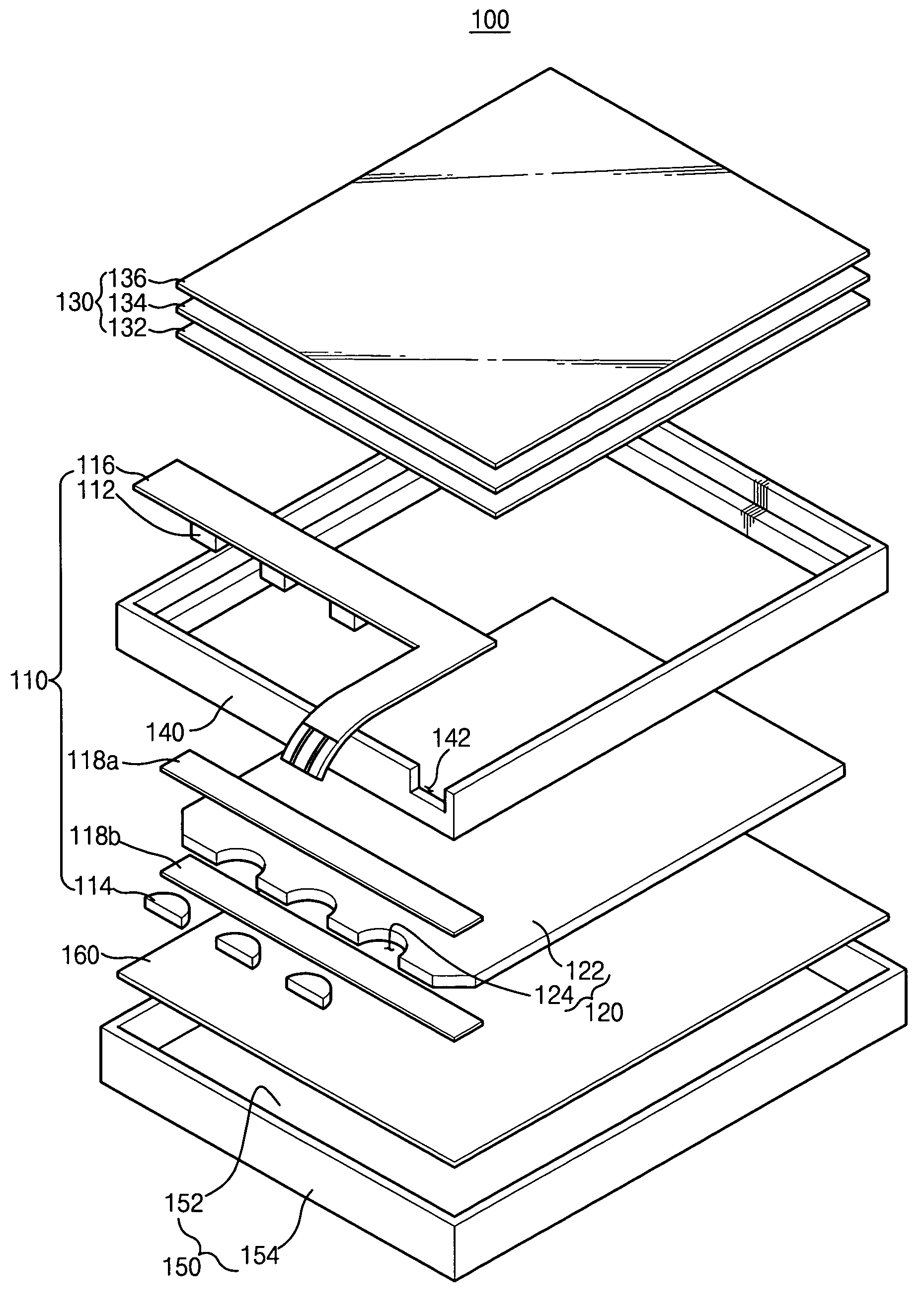
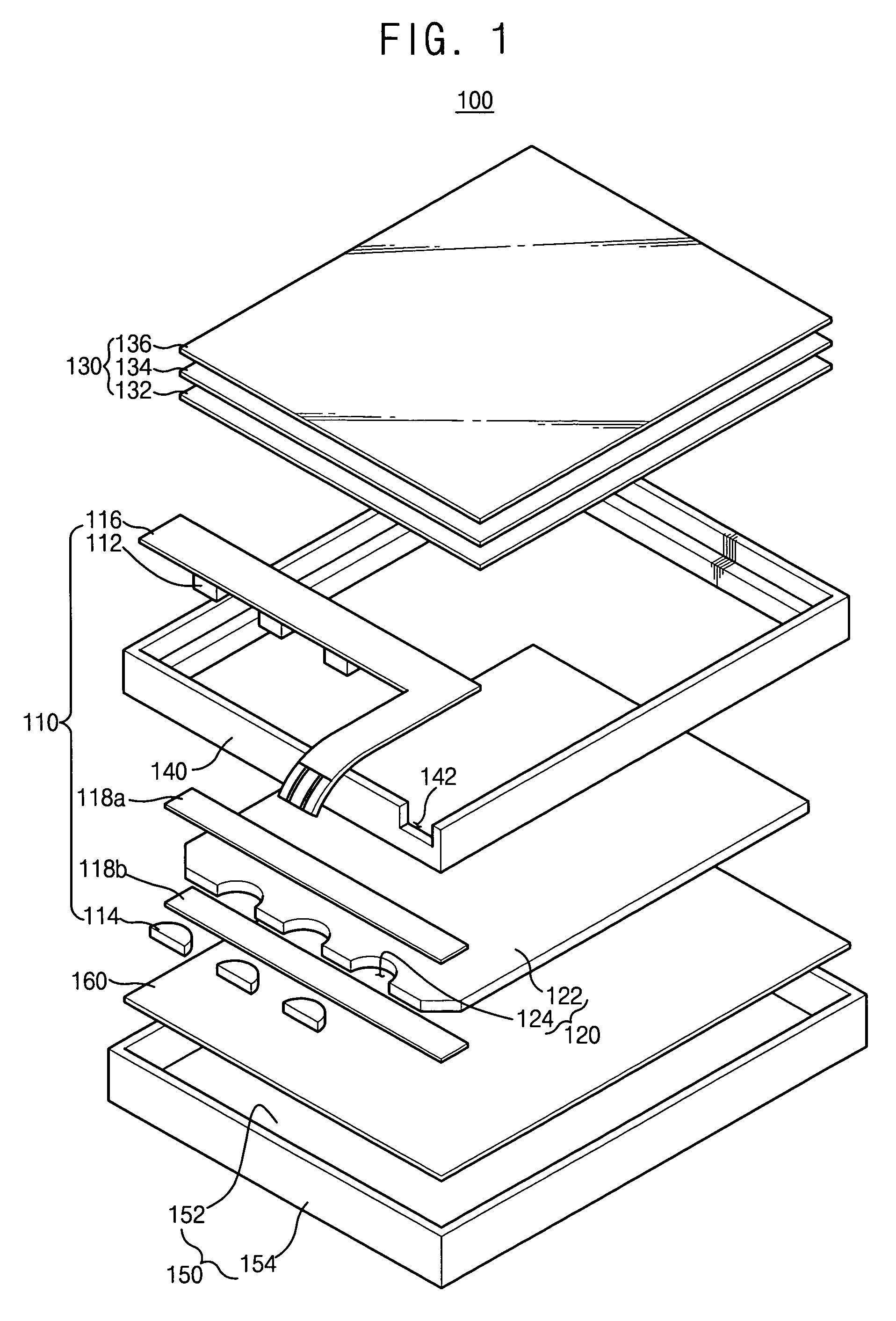
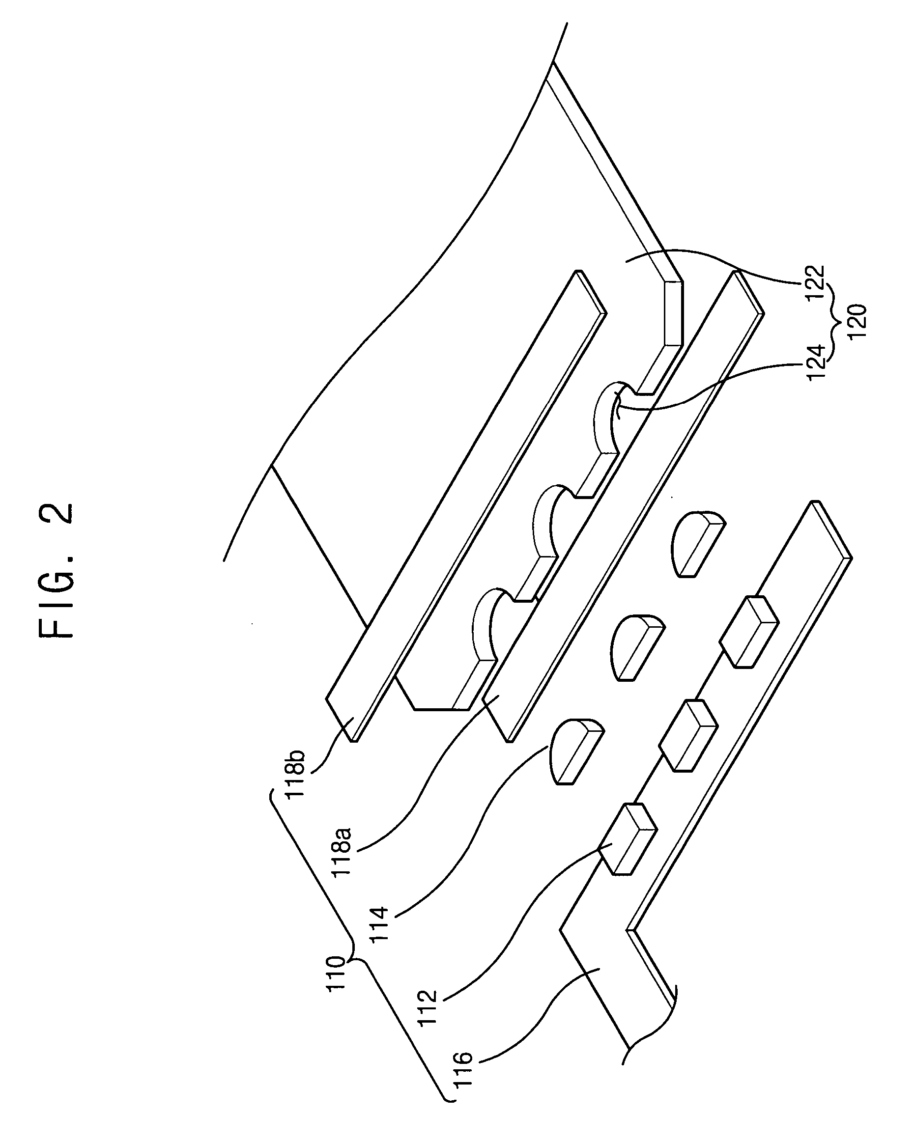
[0015]In accordance with exemplary embodiments, a lens structure having at least one lens is employed in a white light-generating unit so that a divergence angle of a light that propagates from an LED structure having at least one LED into a light guiding plate may be increased. Thus, a dark portion of the light guiding plate may be decreased due to the increased divergence angle. In addition, the LED structure does not require a fluorescent member therefore, the size of the LED structure may be decreased.

Problems solved by technology

However, in the conventional display device, a light generated from the white LED is incident into the light guiding plate at a relatively small divergence angle resulting in a dark portion on the light guiding plate.
In addition, the white LED has a complex structure and is very expensive so that the conventional display device including the white LED may be increased in size thereby potentially increasing its cost of manufacturers.

Method used


Image

  • White light generating unit, backlight assembly having the same and liquid crystal display device having the same
  • White light generating unit, backlight assembly having the same and liquid crystal display device having the same
  • White light generating unit, backlight assembly having the same and liquid crystal display device having the same

Examples


embodiment 1

[0064]FIG. 7 is a plan view illustrating another exemplary embodiment of a backlight assembly according to the present invention. FIG. 7 illustrates a path of a light propagating in a light guiding plate via a lens structure from an LED structure when the lens structure and the light guiding plate are apart from each other. The backlight assembly of the present embodiment is substantially identical to the backlight assembly of Embodiment 1 except for a construction of the lens structure and the light guiding plate. Thus, any further description of substantially similar elements will be omitted.

[0065]Referring to FIG. 7, the backlight assembly includes a lens structure 114 and a light guiding plate 120b. When the lens structure 114 and the light guiding plate 120b are apart from each other, a light generated from an LED structure 112 passes through the lens structure 114. After the light passes through the lens structure 114, the light propagates through an air layer positioned betwe...

embodiment 3

[0084]FIG. 12 is a plan view illustrating another exemplary embodiment of a backlight assembly according to the present invention. FIG. 12 illustrates a path of a light propagating in a light guiding plate via a lens from an LED structure when the lens structure and the light guiding plate are apart from each other. The backlight assembly of the present embodiment is substantially identical to the backlight assembly of Embodiment 3 except for a construction of the lens and the light guiding plate. Thus, any further description for substantially similar elements will be omitted.

[0085]Referring to FIG. 12, when the lens structure 214 and the light guiding plate 220b are apart from each other, a light generated from the LED structure 212 passes through the lens structure 214. After passing through the lens structure 214, the light passes through an air layer between the lens structure 214 and the light guiding plate 220b. After passing through the air layer, the light diverges from a f...


PUM


Abstract

A white light generating unit includes an LED structure and a lens structure. The LED structure generates a light. The lens structure has a convex lens or a concave lens. The lens structure has a fluorescent member that receives the light from the LED structure to emit a white light.

Description

[0001]The present application claims priority to Korean Patent Application No. 2004-79182 filed on Oct. 5, 2004, the contents of which are herein incorporated by reference in its entirety.BACKGROUND OF THE INVENTION[0002]1. Field of the Invention[0003]The present invention relates generally to a white light generating unit, a backlight assembly having the white light generating unit and a liquid crystal display device having the white light generating unit. More particularly, the present invention relates to a white light generating unit capable of generating a white light using a light emitting diode structure, a backlight assembly having the white light generating unit and a liquid crystal display device having the white light generating unit.[0004]2. Description of the Related Art[0005]Generally, a liquid crystal display (LCD) device displays images using electrical and optical characteristics of liquid crystal installed therein. The LCD device has various advantages, for example...

Claims


Application Information

Patent Timeline
Patent Type & Authority Patents(United States)
IPC IPC(8): F21V8/00F21V9/08H01L33/50H01L33/58H01L33/60
CPCG02B6/0026G02B6/003G02B6/0068G02B6/0073G02B6/009G02F1/133603H01L33/505H01L33/507H01L33/58G02F1/1335
Inventor HAN, BYUNG-WOONGKIM, KYU-SEOKCHU, YOUNG-BEELEE, SANG-HEEPARK, YOUNG-HEELEE, JONG-NAM
Owner SAMSUNG DISPLAY CO LTD
Why Eureka
Try Eureka