Electric motor

a technology of electric motors and motors, applied in the direction of magnetic circuit rotating parts, magnetic circuit shapes/forms/construction, windings, etc., can solve the problems of reducing the torque ripple of output torque, the difficulty of reducing the fluctuation of magnetic force and cogging torque, etc., to reduce the torque ripple, the effect of improving the efficiency of the electric motor

Active Publication Date: 2008-04-22
MITSUBA CORP
View PDF17 Cites 13 Cited by
  • Summary
  • Abstract
  • Description
  • Claims
  • Application Information

AI Technical Summary

Benefits of technology

[0009]However, in the electric motor with such a variant core, an interval of the adjacent teeth is different between the respective teeth, which results in the fact that length of the crossover portion of each coil is varied per coil in each winding process. Thus, a magnetic balance between the armature core and magnets is varied in the rotating direction, and it is difficult to decrease fluctuations in a magnetic force and cogging torque caused by each coil and reduce torque ripple of the outputted torque.
[0010]An object of the present invention is to improve efficiency of an electric motor and reduce torque ripple.
[0014]According to the present invention, since the slots accommodating the coils are of at least two types different in shape and are tilted in the rotating direction with respect to the axial direction of the rotating shaft, a lamination factor of the coils wound around the slots can be enhanced and simultaneously a magnetic balance of the armature with respect to the magnets can be uniformized. Thus, the efficiency of the electric motor can be improved, and torque ripple can be reduced. Furthermore, the reduction in the torque ripple allows reductions in vibration and noise occurring at a time of operating the electric motor
[0015]Furthermore, according to the present invention, the winding amount of coils reduced due to a tilt of the slots being tilted in the rotating direction with respect to the axial direction of the rotating shaft can be compensated for by varying the shapes of the slots. Thus, by increasing a tilt angle of each of the slots, torque ripple of the electric motor can be further reduced.
[0016]Still further, according to the present invention, since the tip of the engaging portion is formed at an acute angle, holding characteristic of the coils can be enhanced. Also, since reluctance between the adjacent engaging portions is reduced, it is possible to reduce leakage inductance and enhance rectification of the coils.

Problems solved by technology

However, in the electric motor with such a variant core, an interval of the adjacent teeth is different between the respective teeth, which results in the fact that length of the crossover portion of each coil is varied per coil in each winding process.
Thus, a magnetic balance between the armature core and magnets is varied in the rotating direction, and it is difficult to decrease fluctuations in a magnetic force and cogging torque caused by each coil and reduce torque ripple of the outputted torque.

Method used


Image

  • Electric motor
  • Electric motor
  • Electric motor

Examples


Embodiment Construction

[0025]Embodiments of the present inventions will be described in detail below based on the drawings.

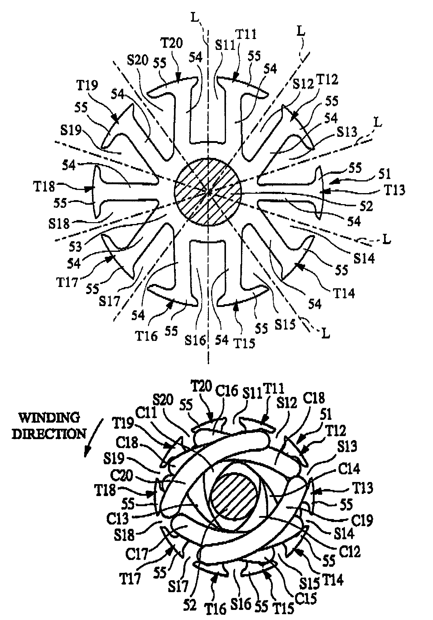
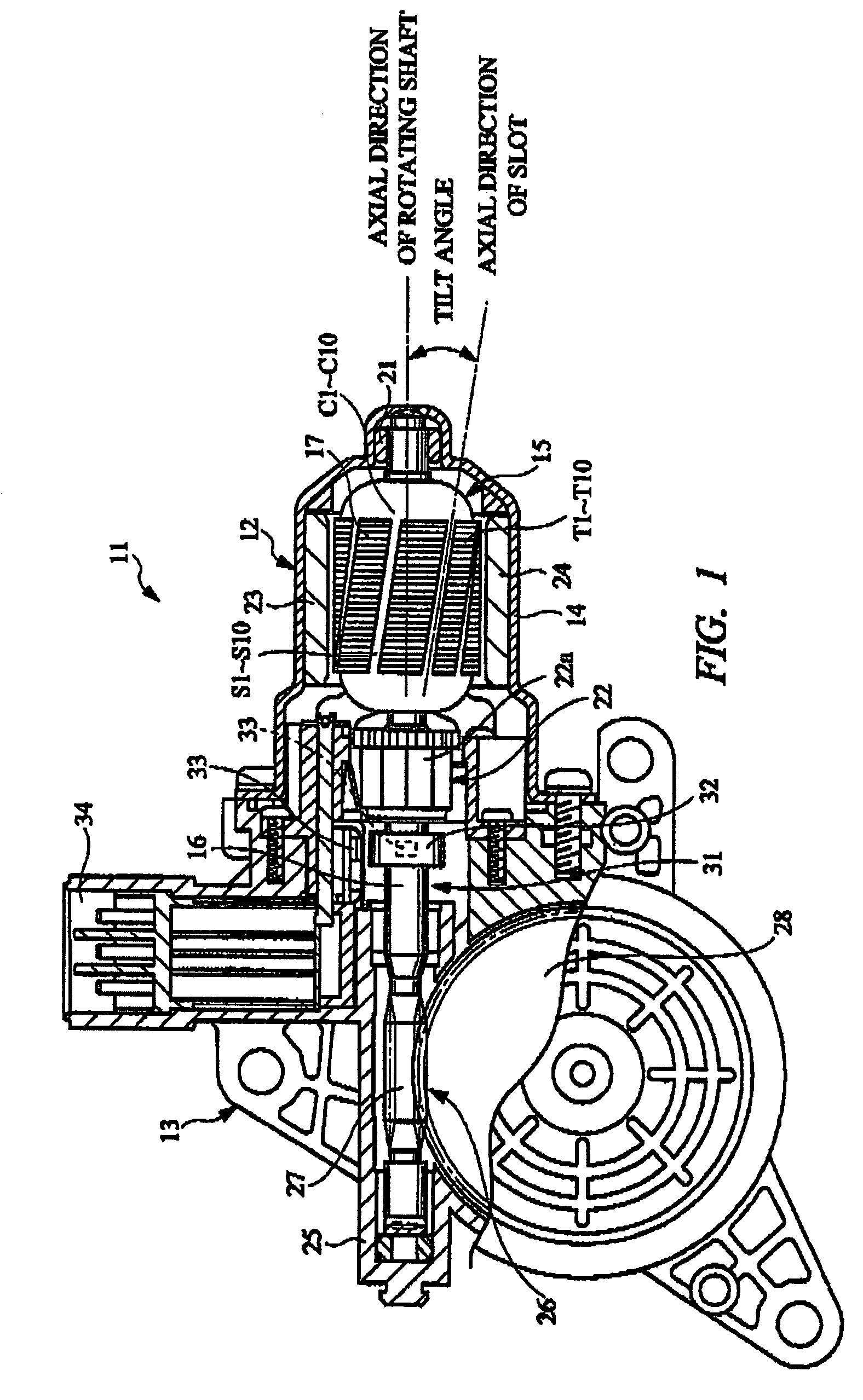
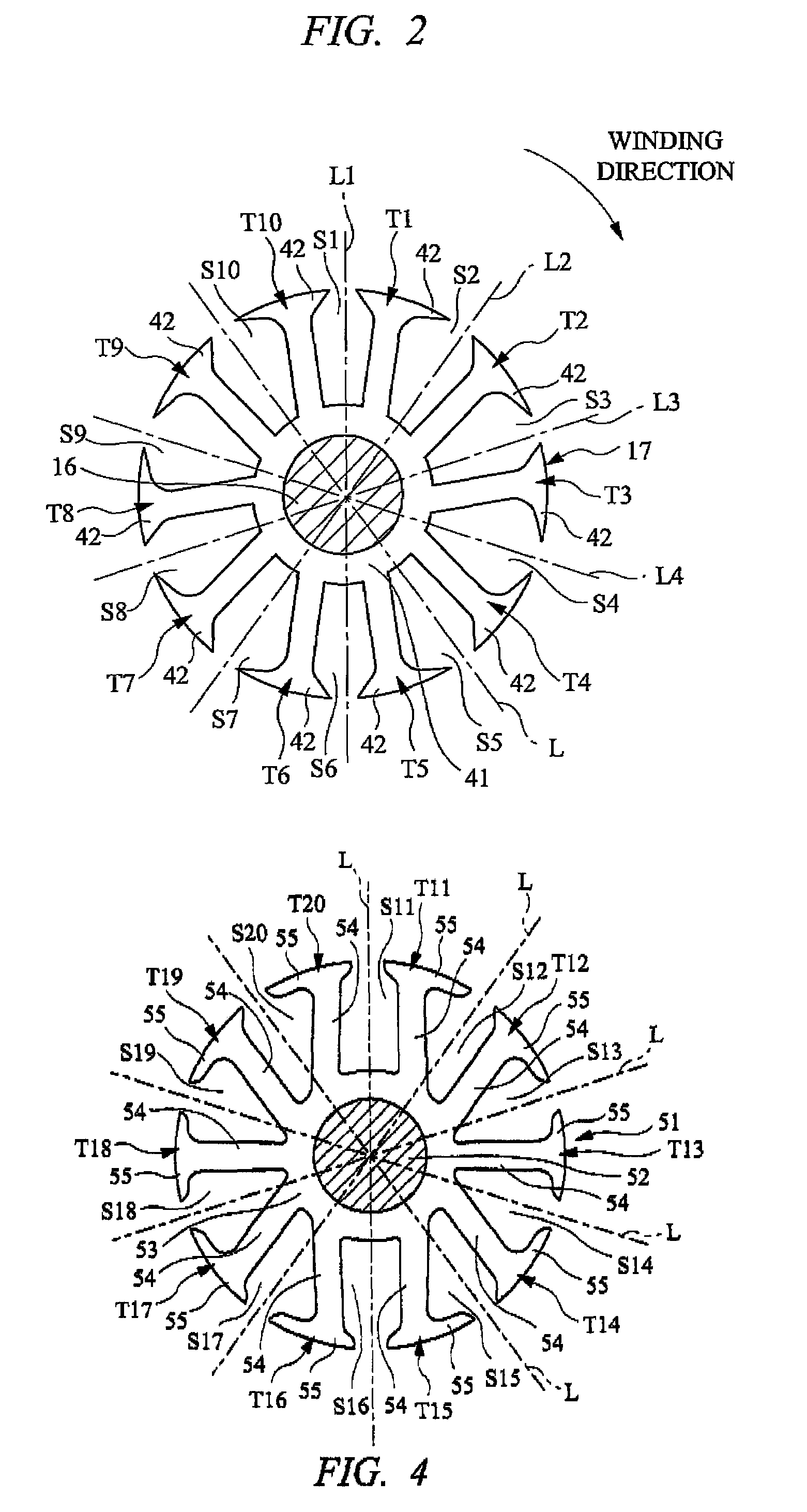
[0026]FIG. 1 is a partially cut section view of a regulator motor with an electric motor according to one embodiment of the present invention. FIG. 2 is a section view showing a shape in which an armature core shown in FIG. 1 is viewed from an axial direction. FIGS. 3A to 3C are section views showing a scheme of winding of coils around the armature core, respectively.

[0027]A regulator motor 11 shown in FIG. 1 is mounted on a door provided in an unshown vehicle for open / close driving of a door glass openably and closably provided to the door. In this case, the door glass is supported openably and closably in a vertical direction of the door via a guiding member, and is also connected to an unshown output shaft of the regulator motor 11 via a regulator. When the regulator motor 11 operates, rotational movement of the output shaft is converted by the regulator to vertical movement of the...


PUM


Abstract

An electric motor has an armature rotatably accommodated inside a motor housing and a pair of magnets fixed to an inner surface of the motor housing so as to face the armature. The armature has an armature core 17 fixed to a rotating shaft 16, and ten slots S1 to S10 formed on the armature core accommodate coils. These slots S1 to S10 are of four types that are different in shape, thereby enhancing a lamination factor of each coil. Also, these slots S1 to S10 are formed so as to be tilted in a rotating direction with respect to an axial direction of the rotating shaft 16. Therefore, a magnetic imbalance caused by the slots S1 to S10 being formed in varying shapes is uniformized.

Description

CROSS-REFERENCE TO RELATED APPLICATIONS[0001]This application is entitled to the benefit of and incorporates by reference essential subject matter disclosed in International Patent Application No. PCT / JP2004 / 012652 filed on Sep. 1, 2004, Japanese Patent Application No. 2003-311289 filed on Sep. 3, 2003, and Japanese Patent Application No. 2003-311290 filed on Sep. 3, 2003.TECHNICAL FIELD[0002]The present invention relates to an electric motor that converts electric energy to mechanical energy via magnetic energy and, more particularly, to an electric motor equipped with an armature core around which coils are wound in a manner of a lap winding.BACKGROUND ART[0003]An electric motor has an armature rotatably accommodated inside a motor housing and a pair of magnets fixed to an inner surface of the motor housing so as to face the armature, and converts a direct current, i.e., electric energy supplied to the armature, to rotation of the armature, i.e., mechanical energy, for output.[000...

Claims


Application Information

Patent Timeline
Patent Type & Authority Patents(United States)
IPC IPC(8): H02K1/00H02K1/22H02K1/26H02K23/40
CPCH02K1/265H02K23/405
Inventor MAITA, SHIGEHIROKAWASHIMA, YOSHICHIKA
Owner MITSUBA CORP
Why Eureka
Try Eureka