Digital diagnostic apparatus and vision system with related methods

a digital diagnostic and vision system technology, applied in the field of electronic devices, can solve the problems of complex systems, large setup time, and complex systems used in production processes to identify dimensional flaws, and achieve the effects of reducing the number of parts, reducing the number of errors, and improving the accuracy of the results

Inactive Publication Date: 2008-04-22
MASTEN OPTO DIAGNOSTICS
View PDF5 Cites 18 Cited by
  • Summary
  • Abstract
  • Description
  • Claims
  • Application Information

AI Technical Summary

Benefits of technology

[0012]1) a high speed, simplistic method for identifying objects, their dimensions, condition and their conformity to specifications;
[0026]15) a light sensor and diagnostic unit that minimizes the requirement for set up time, data or software input and relies primarily on a “compare to standard” method of part or surface diagnostics.

Problems solved by technology

As understood, the prior art machine vision and sensor units used in production processes to identify dimensional flaws, missing parts, and improper assembly are relatively complex, intricate and expensive.
Not only are these systems complex and expensive, they are believed to require considerable setup time.

Method used


Image

  • Digital diagnostic apparatus and vision system with related methods
  • Digital diagnostic apparatus and vision system with related methods
  • Digital diagnostic apparatus and vision system with related methods

Examples


Embodiment Construction

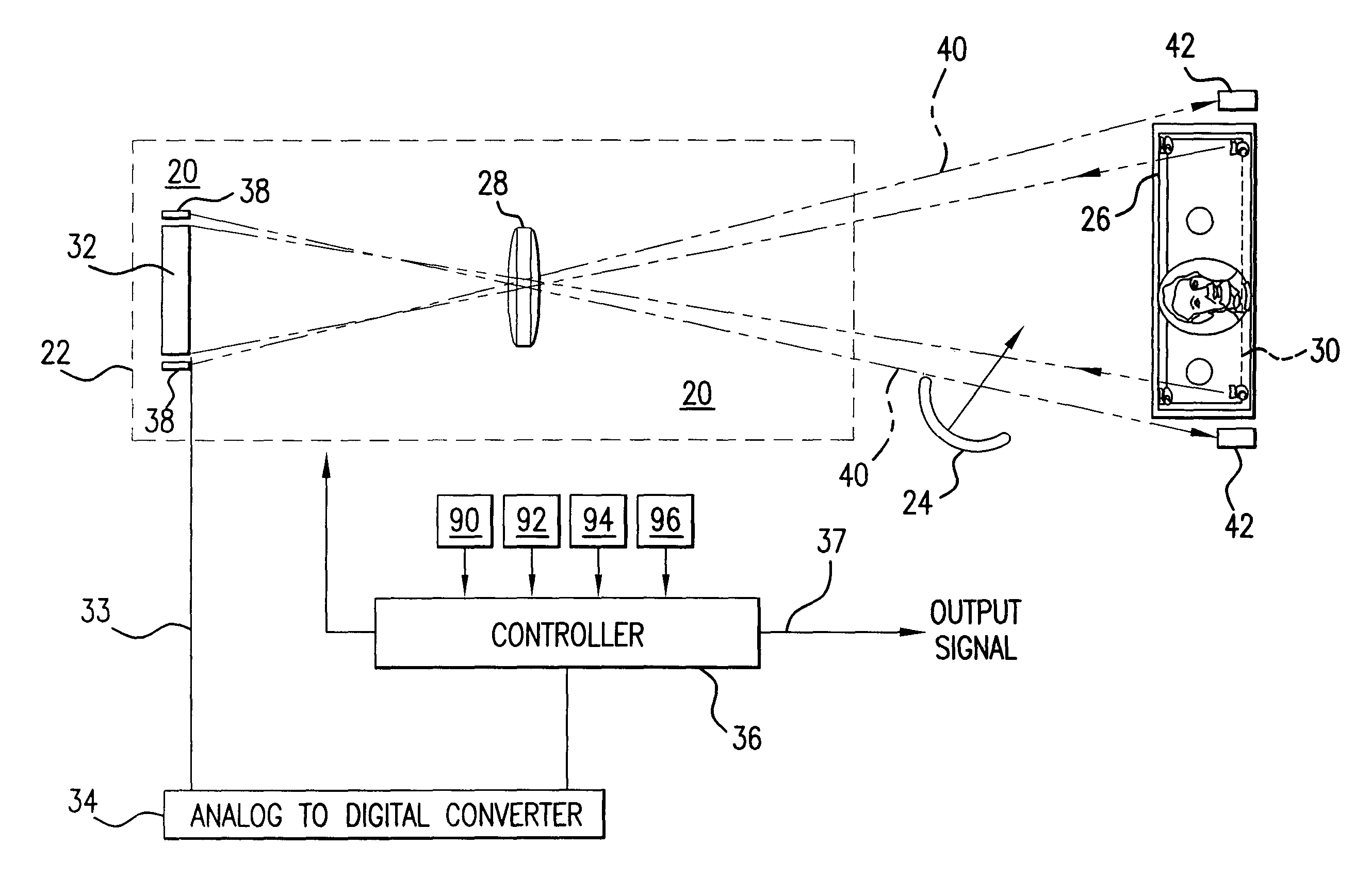
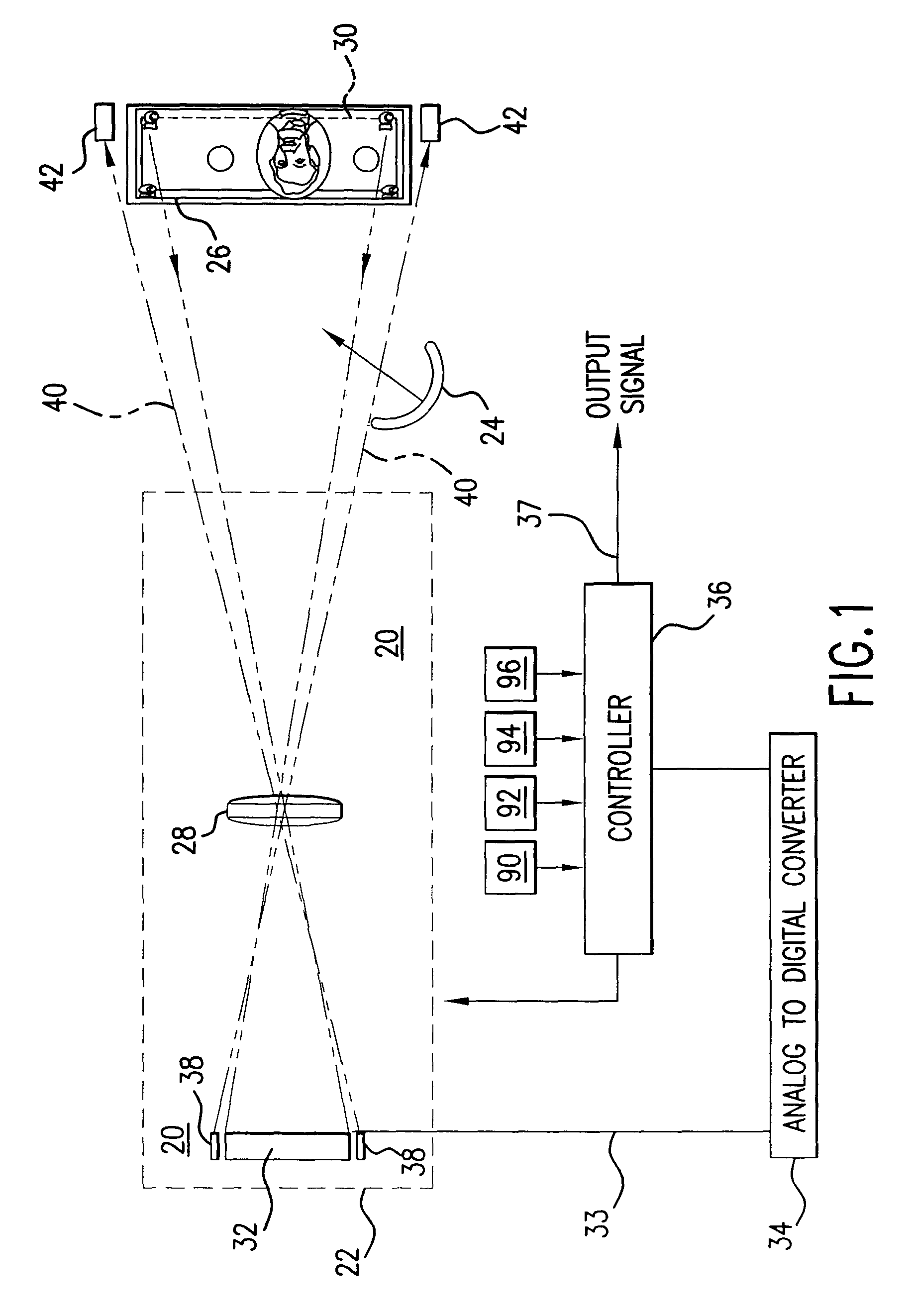
[0033]As depicted in FIG. 1, a preferred embodiment of the sensor or vision system 10 comprises a sensor unit 20 having a housing 22. Within the housing is a lens 28 that receives reflected light from an object 26 whose identity is desired. In this alternative, the object 26 for identification is a five dollar bill. The light may be natural light, or if the unit is mounted in an enclosed bill changer or counter (not shown), the light may be generated by a lamp 24. The lens 28 focuses the reflected light from along a line 30 on the bill to a sensor or linear array 32 such as part no. TSL 1301 from Texas Advanced Optoelectronic Solutions of Plano, Tex. This unit has 102 pixels, each of which comprises a PN junction. In operation, each of these pixels develops a voltage that correlates to the quantity or intensity of a spatial segment of light reflected from along the line 30 on the five dollar bill. The magnitude of the developed voltage of each pixel can be read by a logic chip, cont...


PUM

PropertyMeasurementUnit
speedaaaaaaaaaa
reflectionsaaaaaaaaaa
speedaaaaaaaaaa

Abstract

A high speed, low cost, apparatus and method of identification, examination of objects and quality control of manufactured parts and sheet materials, the apparatus including a comparator having memory storage of data representative of the surface of a first “standard” spatial linear distribution of light and memory storage of data representative of another portion of the surface, and including an algorithm for comparing data of the standard with data representative of the second spatial linear distribution of light reflected from a surface to determine if there is a correlation between the two spatial distributions.

Description

[0001]This application claims the benefit of U.S. Provisional Application No. 60 / 408,711 filed Sep. 6, 2002.FIELD OF THE INVENTION[0002]This invention is primarily directed to an electronic apparatus and method for identifying and quantifying objects, their dimensions, condition or their conformity to specifications. It includes a sensor unit having a digital identifier or diagnostic unit. More particularly, the preferred embodiment is directed to an instrument for diverse functions such as: 1) determination of dimensions and conformity to specifications of parts formed of various materials, 2) inspection for abnormalities of a surface of flat materials including plastic, metal and woven and non-woven web and sheet, 3) identification of the type or quality of surfaces of a sheet material, 4) identification of the denomination of bills in a bill changer or counter and similar functions, and 5) determination of the presence or absence of components in a metal, plastic or wired assembl...

Claims


Application Information

Patent Timeline
Patent Type & Authority Patents(United States)
IPC IPC(8): G06K9/74G01N21/00G06K9/00
CPCG06K9/00G06F18/00
Inventor MASTEN, BILLY R.
Owner MASTEN OPTO DIAGNOSTICS
Why Eureka
Try Eureka