
Printing apparatus

a printing apparatus and printing technology, applied in the direction of digital output to print units, visual presentation using printers, instruments, etc., can solve the problems of printer stopping, difficult to know whether the printer is operating normally, simply taking a fair amount of processing time, etc., and achieve the effect of easy understanding for users

Inactive Publication Date: 2008-04-22
RICOH KK
View PDF14 Cites 42 Cited by
  • Summary
  • Abstract
  • Description
  • Claims
  • Application Information

AI Technical Summary

Benefits of technology

[0013]Accordingly, it is an object of the present invention to provide a printing apparatus in which the above-described drawbacks of the conventional art are eliminated, that is, to provide a printing apparatus that displays the operation of the printing apparatus during their execution in a manner that is easy for the user to understand.
[0014]Another object of the present invention is to provide a printing apparatus that displays which supply tray has been selected when a plurality of supply trays is automatically selected, in a manner that is easy for the user to understand.
[0030]According to the above-described aspects of the present invention, the state of operation of the printing apparatus and the present status of print jobs can be displayed in real time, allowing the user to obtain an accurate understanding of the state of the printing apparatus and eliminating uncertainty over whether the apparatus is functioning properly or not.
[0031]Additionally, the above-described aspects of the present invention provide the following advantages.
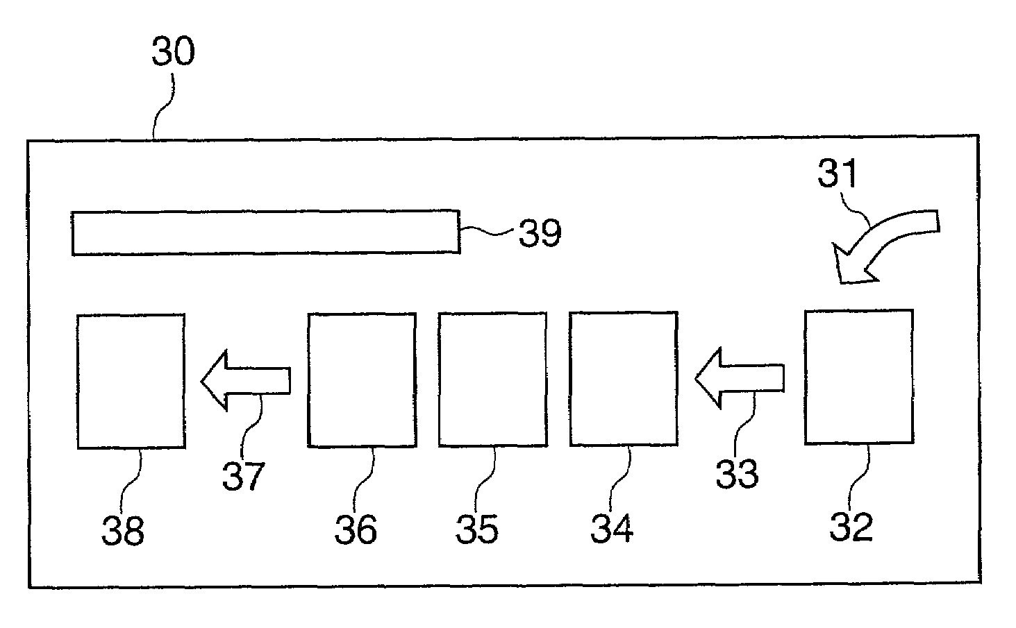
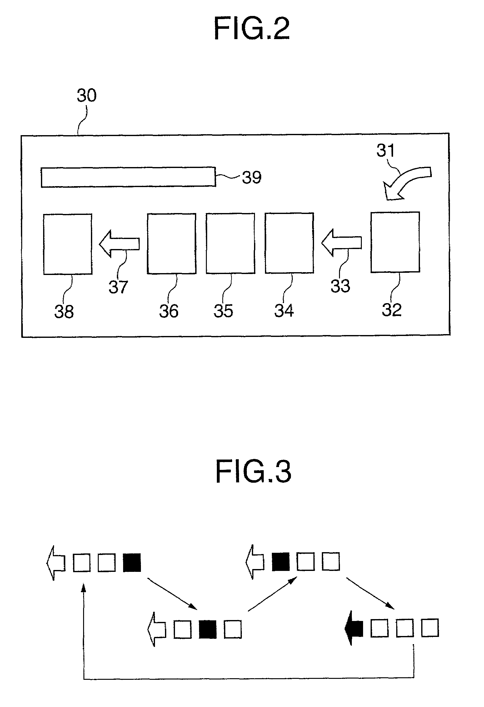
[0032]The animated display provided by the individual indicators for spooling, drawing and printing provide the user with a direct, easy-to-understand way of ascertaining the operating status of the printing apparatus. The display of the amount of unprocessed data aids the user in determining whether or not to input the next print job, and provides a benchmark for adjusting the amount of RAM used for spooling. Displaying in real time the contents of pages in the process of being drawn or printed makes stop commands easier to issue. Moreover, displaying a list of jobs in process together with the number of pages aids in predicting when a desired job will be printed. Also, displaying the location of the supply and exit trays aids in re-supplying the supply tray and in determining where the completed print exits the apparatus.

Problems solved by technology

Nevertheless, in general, the state of the printing apparatus has been difficult to ascertain.
For example, it has been difficult to know whether the printer is operating normally and simply taking a fair amount of processing time, or whether some trouble has occurred and the printer has stopped.
However, in a case in which the printing apparatus is operating normally but is taking time, it is not possible to tell the status of the printing apparatus merely from looking at the printing apparatus or its indicators.
In particular, where the LED state has changed but no message is displayed, it is not always possible to ascertain what that LED is indicating, thus increasing the uncertainty as to what is happening.
Similarly, when the supply tray or the exit tray has been automatically selected, it has been difficult to tell where sheets are being supplied from and where they are being exited to.
However, the above-described conventional solutions do not adequately address the drawbacks of the conventional art.
Specifically, the status of print jobs is displayed merely in such general terms as “waiting” or “printing”, and accordingly, in a case in which, for example, “printing” is displayed and such display does not change for a long time, it is impossible to know whether the printing apparatus is merely taking a long time or some trouble has occurred and the printing apparatus is stopped, thus heightening the uncertainty for the user.
Additionally, in the conventional art it has been necessary to carry out a number of operations in order to obtain a status display, which is inconvenient.

Method used


Image

  • Printing apparatus
  • Printing apparatus
  • Printing apparatus

Examples


Embodiment Construction

[0045]A description will now be given of preferred embodiments of the present invention, with reference to the accompanying drawings. It should be noted that identical or corresponding elements are given identical or corresponding reference numbers in all drawings, with detailed descriptions thereof given once and thereafter omitted.

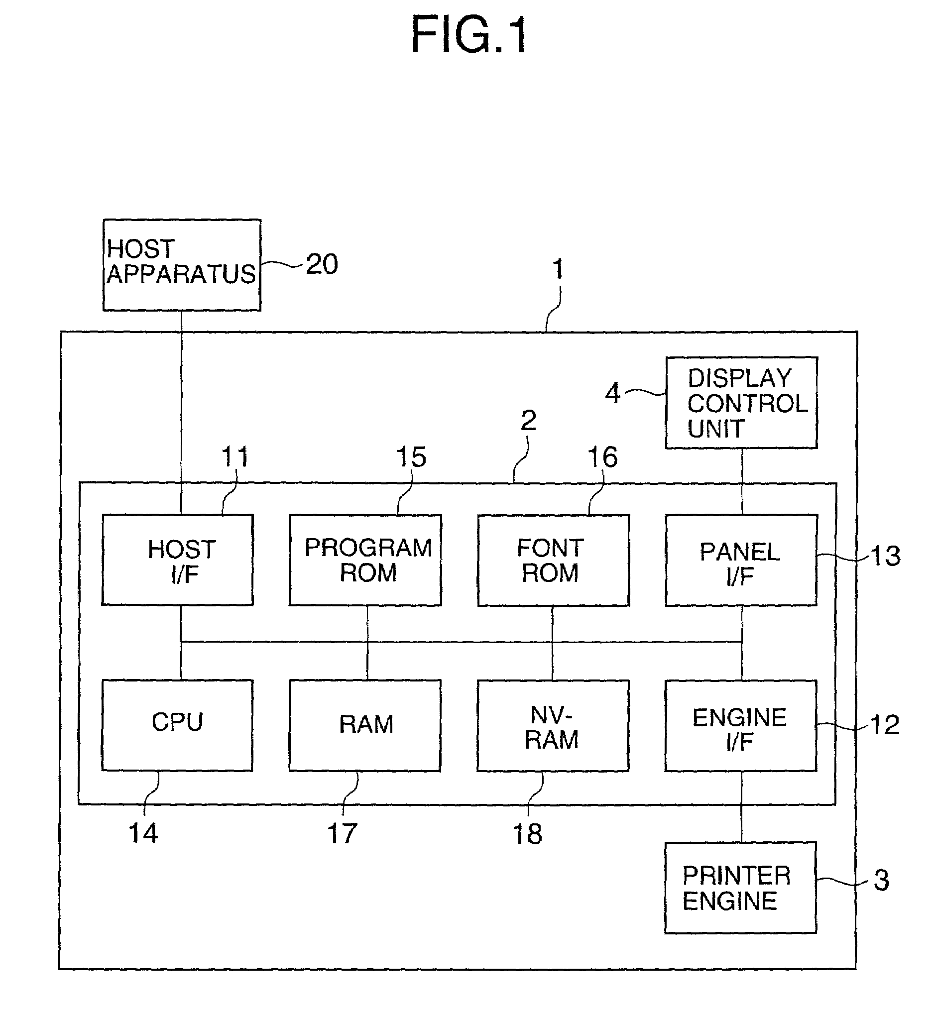
[0046]FIG. 1 is a block diagram illustrating a configuration of a printer apparatus according to one embodiment of the present invention. As shown in FIG. 1, the printing apparatus may be a laser printer 1.

[0047]The laser printer 1 comprises a controller 2, a printer engine 3 and a display / control unit 4. The controller 2 is an apparatus that converts image data from a host apparatus 20 to bit map data (drawing data) and outputs the converted data to the printer engine 3 according to a set control mode and a control code from the host computer 20, and is composed of the following components, namely: a host interface (hereinafter I / F) 11, an engine I / F12,...


PUM


Abstract

A printing apparatus includes an image data input means for receiving input data, image data processing means for processing the image data and drawing the image data in an image memory unit, printing means for forming an image on a transfer sheet using the image data drawn in the image memory unit, and display means for displaying, either dynamically or successively, which process the image data is undergoing at any given moment, beginning with image data reception and ending with image data printing.

Description

BACKGROUND OF THE INVENTION[0001]1. Field of the Invention[0002]The present invention relates to a printing apparatus, and more precisely, to a printing apparatus for printers, digital copiers and facsimile machines.[0003]2. Description of the Related Art[0004]In the conventional printing apparatus for printers and the like, the state or status of the printing apparatus has been indicated by simple messages and the like displayed by a plurality of light emitting diodes and liquid crystal display units. Nevertheless, in general, the state of the printing apparatus has been difficult to ascertain. For example, it has been difficult to know whether the printer is operating normally and simply taking a fair amount of processing time, or whether some trouble has occurred and the printer has stopped.[0005]In the case of an error occurring, an LED or a message to that effect is displayed, so it is possible to understand what is going on with the printing apparatus. However, in a case in wh...

Claims


Application Information

Patent Timeline
Patent Type & Authority Patents(United States)
IPC IPC(8): G06F15/00B41J29/42B41J29/00G03G21/00G06K15/00H04N1/00
CPCG06K15/00G06K15/005G06K15/18
Inventor KITAZAWA, TOSHIO
Owner RICOH KK
Learn More