Gas chromatograph sample injector

a gas chromatograph and injector technology, applied in the field of gas chromatograph analysis, can solve the problems of deteriorating gas chromatograph analysis throughput, time-consuming and labor-intensive manual derivation process, and long time consumption, so as to improve the efficiency and throughput of analysis, improve the efficiency of analysis. the effect of throughput and high throughpu

Active Publication Date: 2008-04-29
SHIMADZU CORP
View PDF3 Cites 5 Cited by
  • Summary
  • Abstract
  • Description
  • Claims
  • Application Information

AI Technical Summary

Benefits of technology

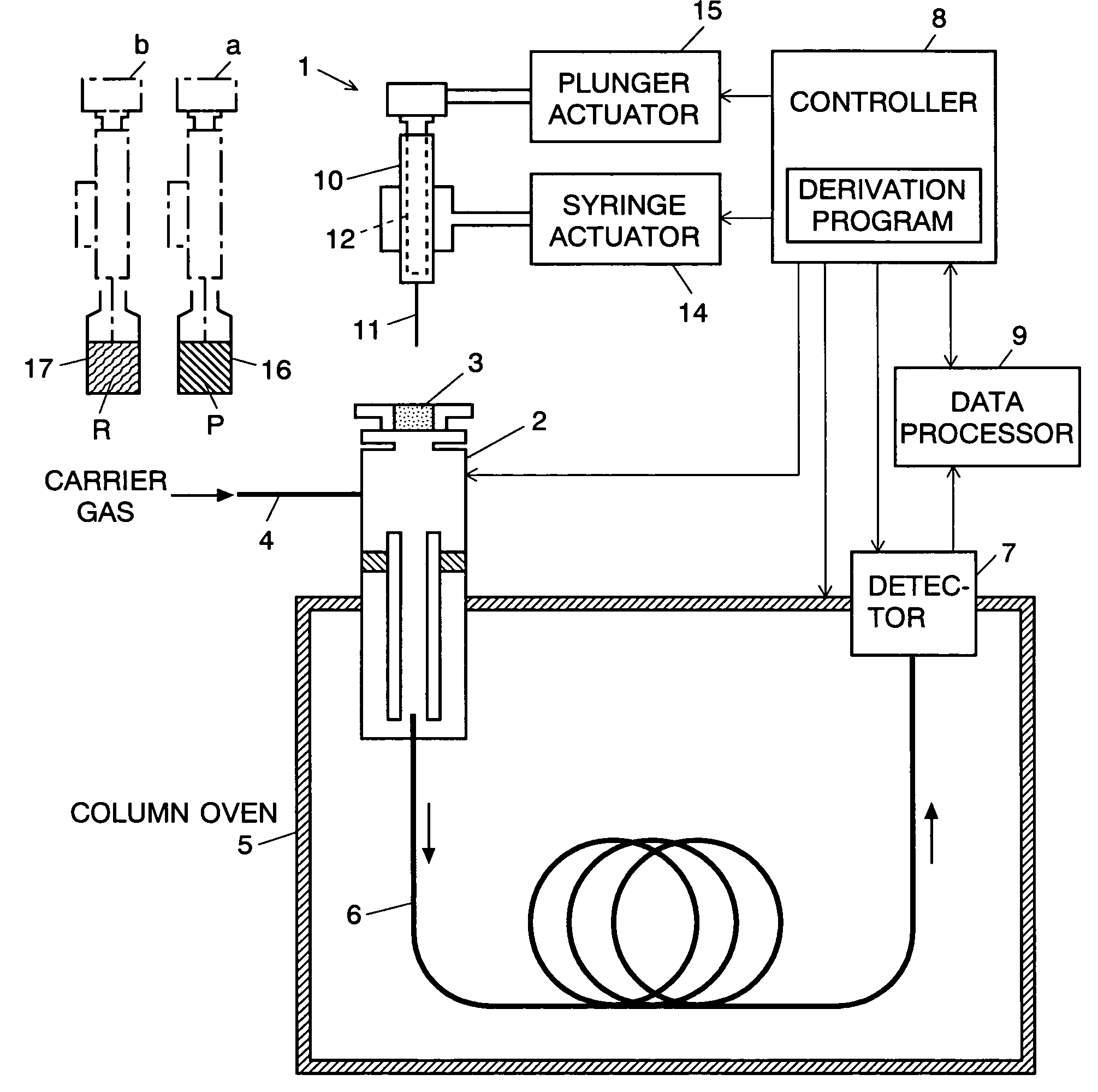
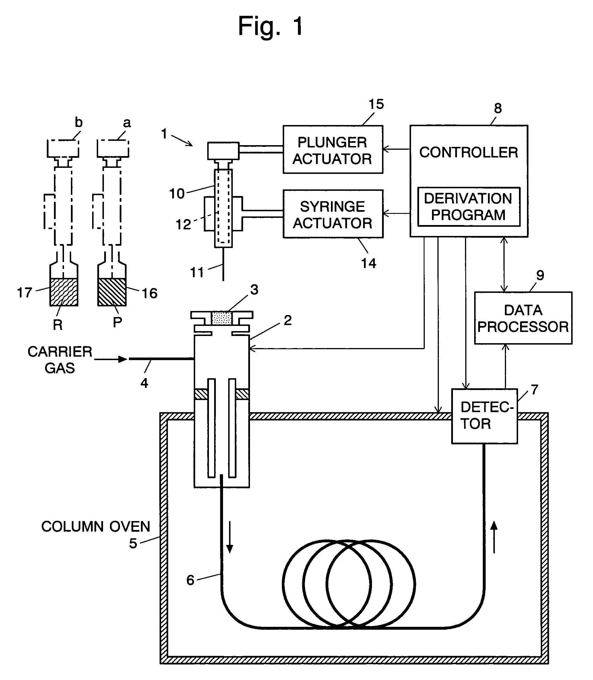
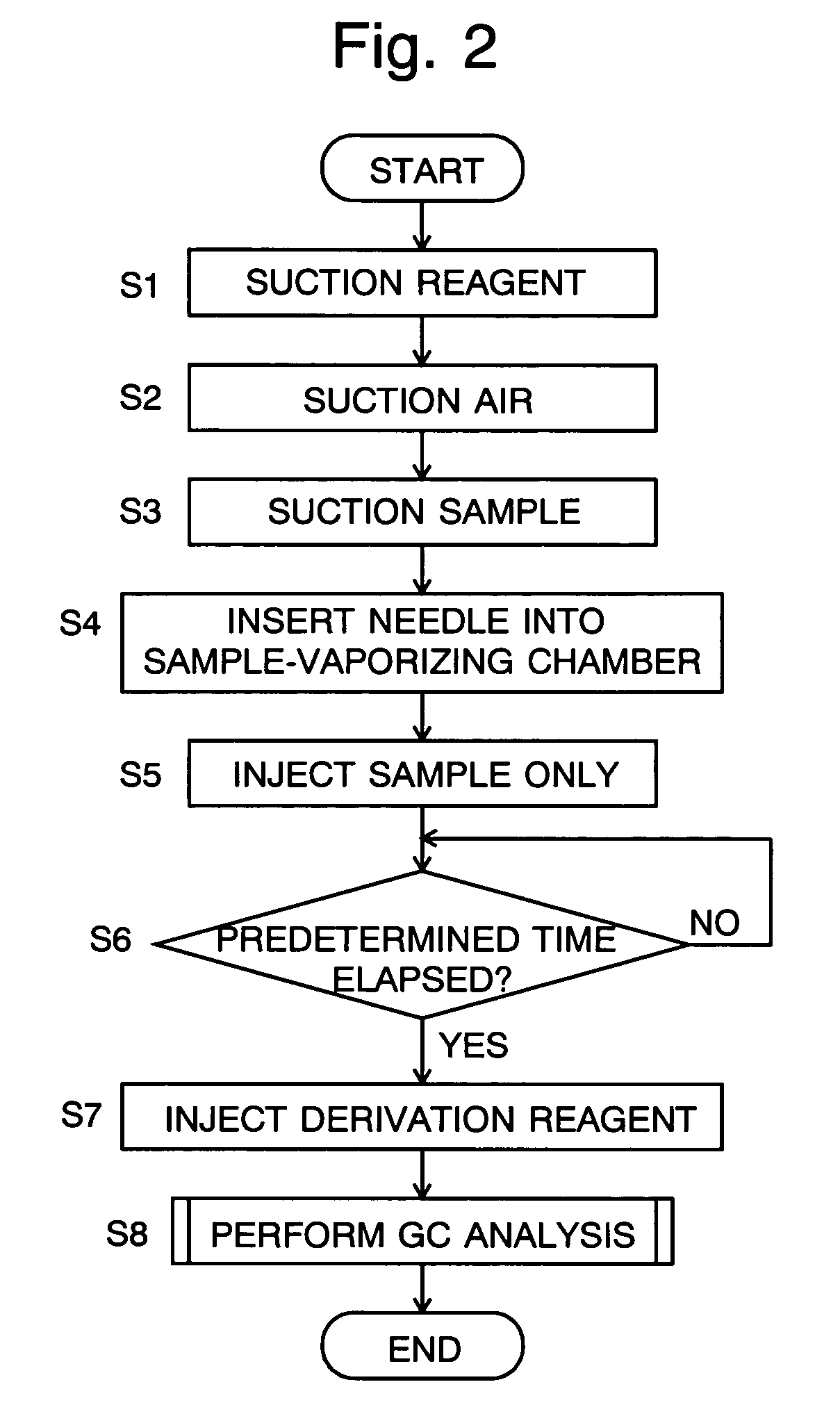
[0015]In the sample injector according to the first mode of the present invention, the actuator, which is controlled by the controller, pulls the plunger while the tip of the needle is immersed in the derivation reagent, whereby a predetermined quantity of the derivation reagent is suctioned into the syringe. Subsequently, the tip of the needle is immersed in the sample, and the actuator further pulls the plunger to suction the sample into the syringe. It is preferable to suction a small quantity of air between the derivation reagent and the sample so as to form an air layer between the derivation reagent and the sample within the syringe. This prevents the derivation reagent from being accidentally mixed with the sample.
[0017]When the vaporized sample enters the column, the target component contained in the sample adheres to the inner wall of the column due to the absorption by the wall, whereas the solvent contained in the sample is conveyed away. The aforementioned period of time is preset long enough for the sample injected into the sample-vaporizing chamber to be vaporized, introduced into the column and absorbed at the inlet of the column. This setting enables the target compound to form a thin, dry film covering the inner wall of the column over an area close to the inlet when the predetermined period of time has elapsed after the injection of the sample. After this state has been reached, the vaporized derivation reagent flows into the column and comes in contact with the compound over a wide area, thereby efficiently converting the compound into a derivative. This derivation process takes place at an inlet section of the column, as opposed to conventional cases where the same process was carried out in a test tube, vial or similar container. Subsequently, a temperature-programmed analysis or a similar analysis is carried out, in which the derivative of the compound is vaporized and conveyed through the column for the gas chromatograph analysis.
[0037]In the gas chromatograph sample injectors according to the first through third modes of the present invention, the derivation of the target compound takes place within the column. This eliminates the troublesome work of manually performing the derivation process on the sample to be injected into the sample-vaporizing chamber, thereby significantly improving the efficiency and throughput of the analysis. The sample injector according to the first mode of the present invention can yield a particularly high level of throughput because it allows the time interval between the injection of the sample into the sample-vaporizing chamber and that of the derivation reagent to be minimized as far as the derivation process effectively works.
[0038]The gas chromatograph sample injectors according to the first through third modes of the present invention also make it unnecessary to prepare special devices and tools for the derivation; all the operator has to do is to prepare a derivation reagent. Thus, the analysis work is further simplified. Furthermore, since there is no need to manually measure and sample the derivation reagent, the operator can avoid health hazards even if the reagent is harmful to humans and also ensure a high level of safety even if the reagent is flammable. With respect to the hardware construction, the sample injector according to the present invention is almost identical to conventional ones; it does not require any additional hardware components for the derivation process. Therefore, it can be constructed as small as conventional ones with a minimal increase in the production cost.

Problems solved by technology

Such a manual derivation process consumes time and labor because it requires the liquid sample to be once vaporized and dried.
Accordingly, the throughput of the gas chromatograph analysis deteriorates if the derivation process is performed; it will take a very long time if there are a large number of specimens to be analyzed.
Also, even if there are only a small number of specimens, the time-consuming method is hardly available in some special cases, such as a test for illegal drugs where the test result should be quickly obtained.
Thus, to enhance the throughput of a gas chromatograph analysis including a derivation process still remains a big challenge.
Also, the conventional method is accompanied by the troublesome work of preparing tools for spraying the dry nitrogen gas, for mixing the sample and the derivation reagent, and for other operations performed for the derivation process.
Moreover, many reagents require careful handling: some are harmful to humans (i.e. poisonous or deleterious), and some are highly flammable.
This requirement limits the scope of people available for this job.
However, this conventional apparatus requires plural thermostatic chambers, a channel selector valve and other devices, which inevitably makes the apparatus large and complex.
Therefore, its production cost is higher than that of ordinary gas chromatographs.

Method used


Image

  • Gas chromatograph sample injector
  • Gas chromatograph sample injector
  • Gas chromatograph sample injector

Examples


example

[0069]A test of the GC analysis was conducted using the gas chromatograph of the above-described embodiment. The target compound was methamphetamine (MA), an illegal drug, and the sample was human urine containing that compound. Methamphetamine as is can be detected only with a very low level of sensitivity by GC analysis. Therefore, it is necessary to convert it into a derivative. In this test, N-Methyl-bis[trifluoroacetamide (MBTFA) was used as the derivation reagent. The test showed that the gas chromatograph constructed as described previously could efficiently produce a derivative in which the active proton contained in the amine base of the methamphetamine was replaced with TFA. FIG. 5 shows a mass chromatogram obtained by analyzing the derivative with a mass spectrometer. Thus, the derivative (MA-TFA) obtained by the derivation process can be detected with high sensitivity, which enables methamphetamine to be identified and determined with high accuracy.

[0070]Tests of this ki...


PUM

PropertyMeasurementUnit
timeaaaaaaaaaa
temperatureaaaaaaaaaa
vaporizing temperatureaaaaaaaaaa

Abstract

In a sample injector for a gas chromatograph, the present invention improves the throughput of a GC analysis including the derivation of a target compound and reduces the tedious work of handling a reagent for the derivation. According to the present invention, a derivation reagent R is suctioned into a microsyringe 10, after which a small amount of air and a sample P to be analyzed are successively suctioned so that the reagent, the air and the sample are held in this order, from top to bottom. Then, the needle 11 of the microsyringe 10 is inserted through the septum 3 into the sample-vaporizing chamber 2, and the plunger 12 is pushed halfway through so that only the sample is injected into the sample-vaporizing chamber 2. The sample thus injected is quickly vaporized into a gas sample and introduced into the column 6, where the target compound contained in the gas sample adheres to the inner wall of an inlet section of the column 6. When several seconds have passed after the injection of the sample, the plunger 12 is further pushed down to inject the reagent into the sample-vaporizing chamber 2. Then, the reagent is turned into gas and introduced into the column 6, where the reagent reacts with the compound to produce a derivative. Subsequently, the temperature of the column 6 is raised to carry out a GC analysis.

Description

[0001]The present invention relates to a sample injector for injecting a sample into a sample-vaporizing chamber located at the inlet of a column of a gas chromatograph. More specifically, it relates to a sample injector for a gas chromatograph used for analyzing a sample that has to be, or should be preferably, converted into a derivative.BACKGROUND OF THE INVENTION[0002]In an analysis using a gas chromatograph, the compound to be analyzed is sometimes converted into a derivative that is easier to analyze or detectable with higher sensitivity, if the compound as is cannot be detected at all or is detectable only with low sensitivity and accuracy. Conversion of a compound into a derivative uses a reagent that causes various kinds of chemical reactions with a functional group of the compound to be analyzed. Examples of the derivation process are silylation, alkyl-esterification, acrylation and dimethylsilylation.[0003]Derivation of a sample containing a target compound generally incl...

Claims


Application Information

Patent Timeline
Patent Type & Authority Patents(United States)
IPC IPC(8): G01N30/02
CPCG01N30/24G01N2030/025G01N2030/126
Inventor TSUCHIHASHI, HITOSHIMIKI, AKIHIROKATAGI, MUNEHIRONISHIKAWA, MAYUMIZAITSU, KEI
Owner SHIMADZU CORP
Why Eureka
Try Eureka