Multiple light source illumination for image display systems

a multi-source, light source technology, applied in the direction of instruments, lighting and heating apparatus, fibre light guides, etc., can solve the problems of limited amount of light within a particular wavelength range that may be accepted by the spatial light modulator, insufficient power of light originating from light sources emitting narrow bands of light to enable the light modulator, etc., to achieve the effect of increasing the intensity of ligh

Active Publication Date: 2008-04-29
TEXAS INSTR INC
View PDF12 Cites 3 Cited by
  • Summary
  • Abstract
  • Description
  • Claims
  • Application Information

AI Technical Summary

Benefits of technology

[0003]In one embodiment, a method for transmitting light in an image display system includes generating a first cone of light from a first light source. The first cone of light includes a plurality of light beams. A first portion of the first cone is projected in an illumination path. A second portion of the first cone is projected at a surface of a reflector. The second portion of the first cone is reflected to project the second portion of the first cone in the illumination path. The first and second portions of the first cone are received at an entrance of an integrator rod. The second portion of the first cone increases the intensity of light received by the integrator rod.
[0004]Depending on the specific features implemented, particular embodiments of the present invention may exhibit some, none, or all of the following technical advantages. A technical advantage may be that beams of light that are emitted outside the cone of acceptance of the modulator may be reflected such that they are redirected at the integrator rod at an angle within the cone of acceptance. As a result, the intensity of light may be increased from a light source without exceeding the etendue of the modulator. Another technical advantage may be that because beams of light may be redirected, multiple light sources may be simultaneously operated without exceeding the etendue limits of the modulator. As a result, substantially brighter images may be projected.
[0005]A further technical advantage may be that the reflector positioned between a light source and an integrator rod may provide a reference point from which the light source or light sources may be mounted. Accordingly, the reflector may provide a reference point from which one or more light sources may be mounted.

Problems solved by technology

Conventional spatial light modulators are limited by their etendue, which dictates the energy available to the system.
Specifically, the amount of light within a particular wavelength range that may be accepted by the spatial light modulator is limited by the etendue of the system.
Light originating from light sources emitting narrow bands of light are typically not powerful enough to enable the light modulators to generate a correctly colored or sufficiently bright image.

Method used


Image

  • Multiple light source illumination for image display systems
  • Multiple light source illumination for image display systems
  • Multiple light source illumination for image display systems

Examples


Embodiment Construction

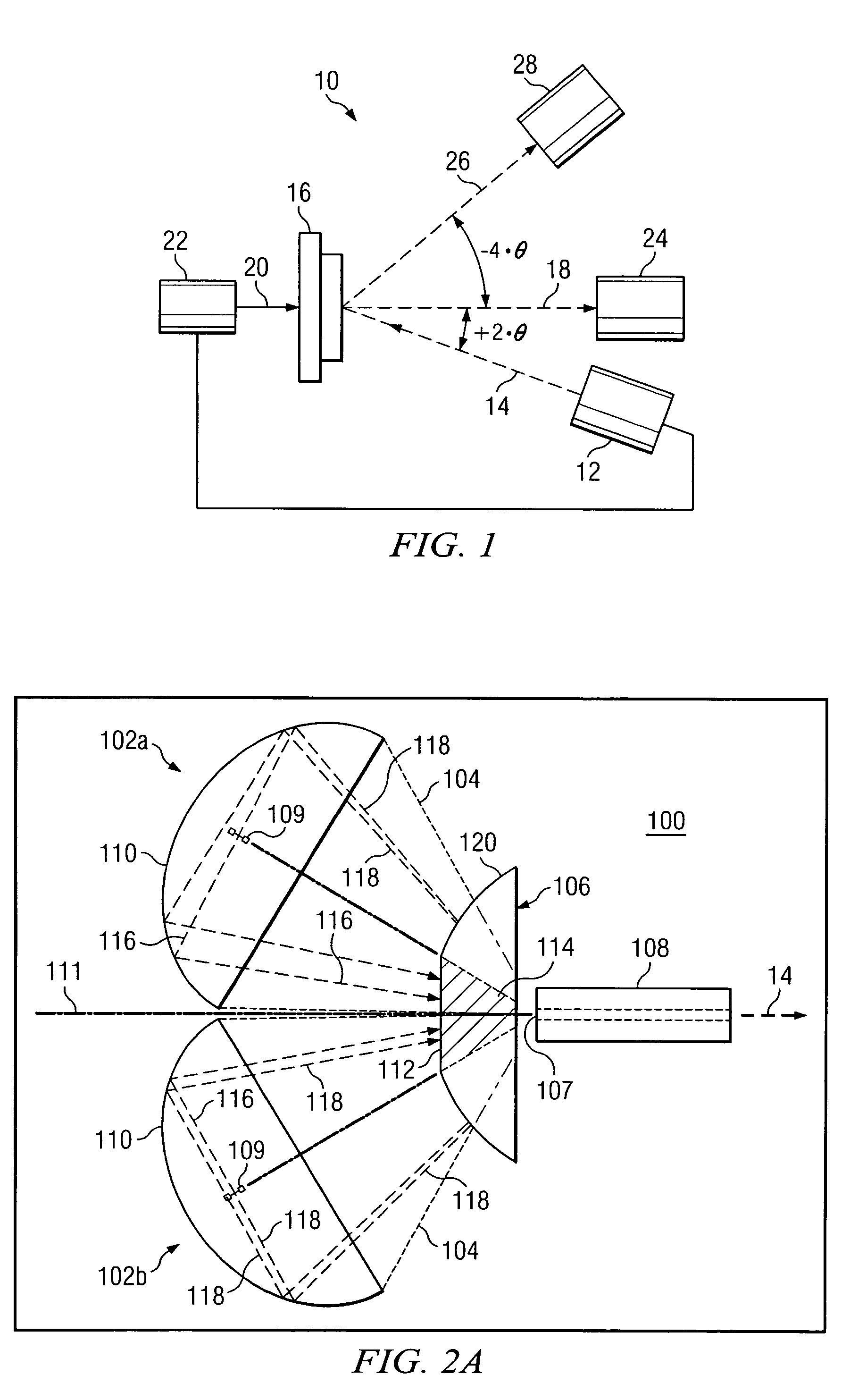
[0011]FIG. 1 is a block diagram of one embodiment of a portion of a projection display system 10. In this example, projection display system 10 includes a light source module 12 capable of generating illumination light beams 14. Light beams 14 are directed from light source module 12 to a modulator 16. Modulator 16 may comprise any device capable of selectively communicating at least some of the received light beams along a projection light path 18. In various embodiments, modulator 16 may comprise a spatial light modulator, such as, for example, a liquid crystal display or a light emitting diode modulator.

[0012]In this particular embodiment, modulator 16 comprises a digital micro-mirror device (DMD). The DMD is a micro electromechanical device comprising an array of hundreds of thousands of tilting micro-mirrors. In a flat state, each micro-mirror may be substantially parallel to projection lens 24. From the flat state, the micro-mirrors may be tilted, for example, to a positive or...


PUM


Abstract

A method for transmitting light in an image display system includes generating a first cone of light from a first light source. The first cone of light includes a plurality of light beams. A first portion of the first cone is projected in an illumination path. A second portion of the first cone is projected at a surface of a reflector. The second portion of the first cone is reflected to project the second portion of the first cone in the illumination path. The first and second portions of the first cone are received at an entrance of an integrator rod. The second portion of the first cone increases the intensity of light received by the integrator rod.

Description

TECHNICAL FIELD OF THE INVENTION[0001]This invention relates in general to image display systems, and more particularly to optical systems implementing micro-mirror based projection display systems.BACKGROUND[0002]Spatial light modulators used in projection display systems are capable of projecting image details from media sources such as HDTV, DVD, and DVI. Conventional spatial light modulators are limited by their etendue, which dictates the energy available to the system. Specifically, the amount of light within a particular wavelength range that may be accepted by the spatial light modulator is limited by the etendue of the system. Light originating from light sources emitting narrow bands of light are typically not powerful enough to enable the light modulators to generate a correctly colored or sufficiently bright image.SUMMARY OF THE INVENTION[0003]In one embodiment, a method for transmitting light in an image display system includes generating a first cone of light from a fi...

Claims


Application Information

Patent Timeline
Patent Type & Authority Patents(United States)
IPC IPC(8): F21V7/04G03B21/28
CPCG02B27/0994G02B6/0006G02B27/09G02B27/18
Inventor DEWALD, DUANE S.PENN, STEVEN M.
Owner TEXAS INSTR INC
Why Eureka
Try Eureka