Scroll type compressor with an enhanced sealing arrangement

a compressor and rolling type technology, applied in the direction of machines/engines, liquid fuel engines, positive displacement liquid engines, etc., can solve the problems of block being quite possible to be lifted, unable to build up the pressure, and unable to lift the gliding block, so as to improve the sealing arrangement and avoid leakage , the effect of facilitating the assembly process in production

Active Publication Date: 2008-04-29
IND TECH RES INST
View PDF8 Cites 39 Cited by
  • Summary
  • Abstract
  • Description
  • Claims
  • Application Information

AI Technical Summary

Benefits of technology

[0007]Accordingly, it is an object of the present invention to provide a scroll type compressor with an enhanced sealing arrangement which can avoid leakage, make easy the assembly process in production, and merchandise the compressor.
[0008]In the present invention, the scroll type compressor with an enhanced sealing arrangement comprises a housing, a bracket body, a partition block, a pair of scrolls, a gliding block, two sealing rings and a plurality of air chambers. The housing for forming an internal accommodation space to accommodate the bracket body further has an inlet and an outlet. The partition block located above the bracket body in the housing separates the accommodation space into a high-pressure chamber and a low-pressure chamber. The scroll pair located between the partition block and the bracket body includes a fixed scroll and a rotary scroll to mesh the fixed scroll. A circular receiving chamber located on top of the fixed scroll further including a first chamber and a second chamber, where the first chamber located above the second chamber is larger than the second chamber in diameter. The gliding block located at a center portion on top of the fixed scroll further includes a first part and a neighboring second part. The first part also located above the second part is larger than the second part in diameter. Upon such an arrangement, the first part of the gliding block can locate above the first chamber, while the second part locates above the second chamber. By matching the gliding block and the scroll pair, a plurality of air chambers can be formed between the fixed scroll and the rotary scroll. Also, by providing pressure variations in these air chamber, the gliding block can be forced to glide.
[0011]By providing the foregoing design criteria to the sealing rings, the load-regulating apparatus (i.e. the scroll type compressor) can be protected from the leakage.

Problems solved by technology

However, a clear drawback of such an arrangement is that the force to lift the gliding block is close to zero at time of cranking up the compressor or at times when the compression ratio is too low.
Under such situations, the gliding block is quite possible unable to overcome the friction and the weight itself to motion upwardly, and thus leakage or failure of building up the pressure may be expected.
On the other hand, when the compression ratio is too high, the resultant force from the gliding block and the spring element may make the gliding block unable to motion downwardly so as to relieve part of the load, and thus the reliability of the compressor is definitely degraded.
In US Pat. Pub. No. 2004 / 0126246, the difficulty in assembling the combination of the gliding block and the O ring into the receiving chamber makes impossible the mass production of the compressor.
Also, in assembling the combination, the O ring is vulnerable to be cut by the chamber and thus may be damaged to induce further leakage which will definitely affect the service life and the reliability of the compressor.

Method used


Image

  • Scroll type compressor with an enhanced sealing arrangement
  • Scroll type compressor with an enhanced sealing arrangement
  • Scroll type compressor with an enhanced sealing arrangement

Examples


Embodiment Construction

[0021]The invention disclosed herein is directed to a scroll type compressor with an enhanced sealing arrangement. In the following description, numerous details are set forth in order to provide a thorough understanding of the present invention. It will be appreciated by one skilled in the art that variations of these specific details are possible while still achieving the results of the present invention. In other instance, well-known components are not described in detail in order not to unnecessarily obscure the present invention.

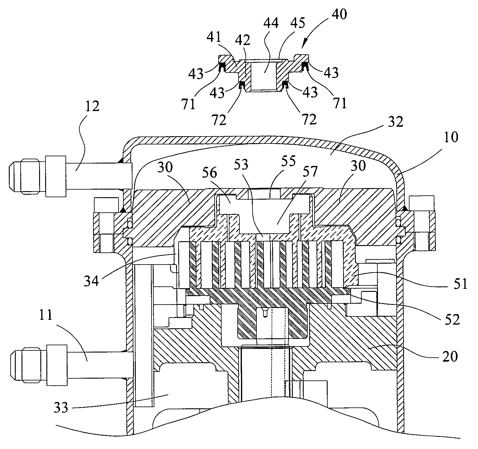
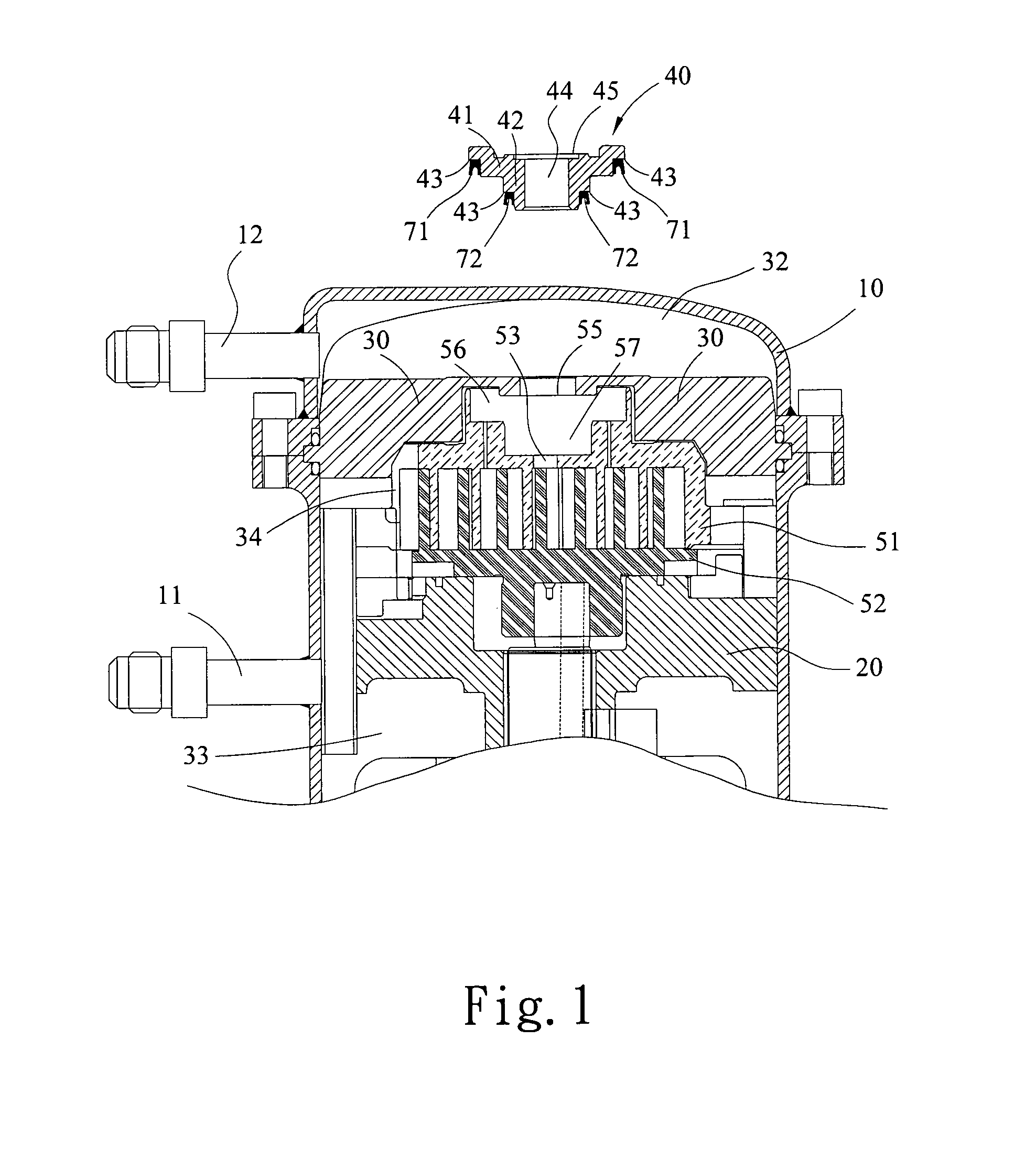
[0022]Referring now to FIG. 1, a top portion of a preferred embodiment of the scroll type compressor with an enhanced sealing arrangement in accordance with the present invention is vertically cross sectional shown. The scroll type compressor with an enhanced sealing arrangement comprises a housing 10, a bracket body 20, a partition block 30, a gliding block 40, a pair of scrolls 51,52, and a plurality of air chambers. The housing 10 further includes an...


PUM


Abstract

A scroll type compressor with an enhanced sealing arrangement includes two sealing rings, mounted one between a first part of a gliding block and a first chamber of a fixed scroll and another one between a second part of the gliding block and a second chamber of the fixed scroll, respectively. The sealing ring has a U-shape cross section characterized in having a center depth smaller than half of a total height of the cross section. By providing such sealing rings, damage in mounting the sealing rings can be reduced to a minimum, possible leakage from the damage can be avoided, the assembly process in producing the compressor can be improved, and the compressor can be successfully merchandized.

Description

BACKGROUND OF THE INVENTION[0001](1) Field of the Invention[0002]The invention relates to a sealing arrangement particularly applied to the scroll type compressor to adjustably avoid leakage in operation.[0003](2) Description of the Prior Art[0004]In the art, while in cranking up a compressor, a rapid pressure boost is required to prevent the working fluid from possible stroking back. Also, the pressure shall be controlled in a reign so that the accumulated pressure won't be too high to damage the scrolls or the compression elements of the compressor, especially to those with a high compression ratio.[0005]In U.S. Pat. No. 6,059,549, an improved high-low pressure chamber sealing arrangement for a volute compressor is disclosed, in which a single air chamber is formed by coupling a gliding block and scrolls. As the compressor is actuated, the gliding block can be pushed upwardly by the pressure variation in the air chamber and the spring force to support the partition block, such tha...

Claims


Application Information

Patent Timeline
Patent Type & Authority Patents(United States)
IPC IPC(8): F04C18/02F04C2/00
CPCF04C27/005
Inventor LIANG, KUN-YIHUANG, SHU-ERYANG, CHUN-CHUNGCHEN, HUNG-CHICHANG, YU-CHOUNGWANG, BO-CHIN
Owner IND TECH RES INST
Why Eureka
Try Eureka