Method of screening the magnetic field generated by an electrical power transmission line and electrical power transmission line so screened

Inactive Publication Date: 2008-04-29
PRYSMIAN CAVI E SISTEMI ENERGIA
View PDF14 Cites 24 Cited by
  • Summary
  • Abstract
  • Description
  • Claims
  • Application Information

AI Technical Summary

Benefits of technology

[0014]The Applicant has found that the magnetic shielding properties of a two-pieces cond

Problems solved by technology

In particular, the Applicant has observed that when an electrical connection is defined through a flat surface contact, this

Method used


Image

  • Method of screening the magnetic field generated by an electrical power transmission line and electrical power transmission line so screened
  • Method of screening the magnetic field generated by an electrical power transmission line and electrical power transmission line so screened
  • Method of screening the magnetic field generated by an electrical power transmission line and electrical power transmission line so screened

Examples


example 1

[0086]The Applicant has measured the magnetic field generated above ground by a buried electrical line as previously described, in several different operating conditions.

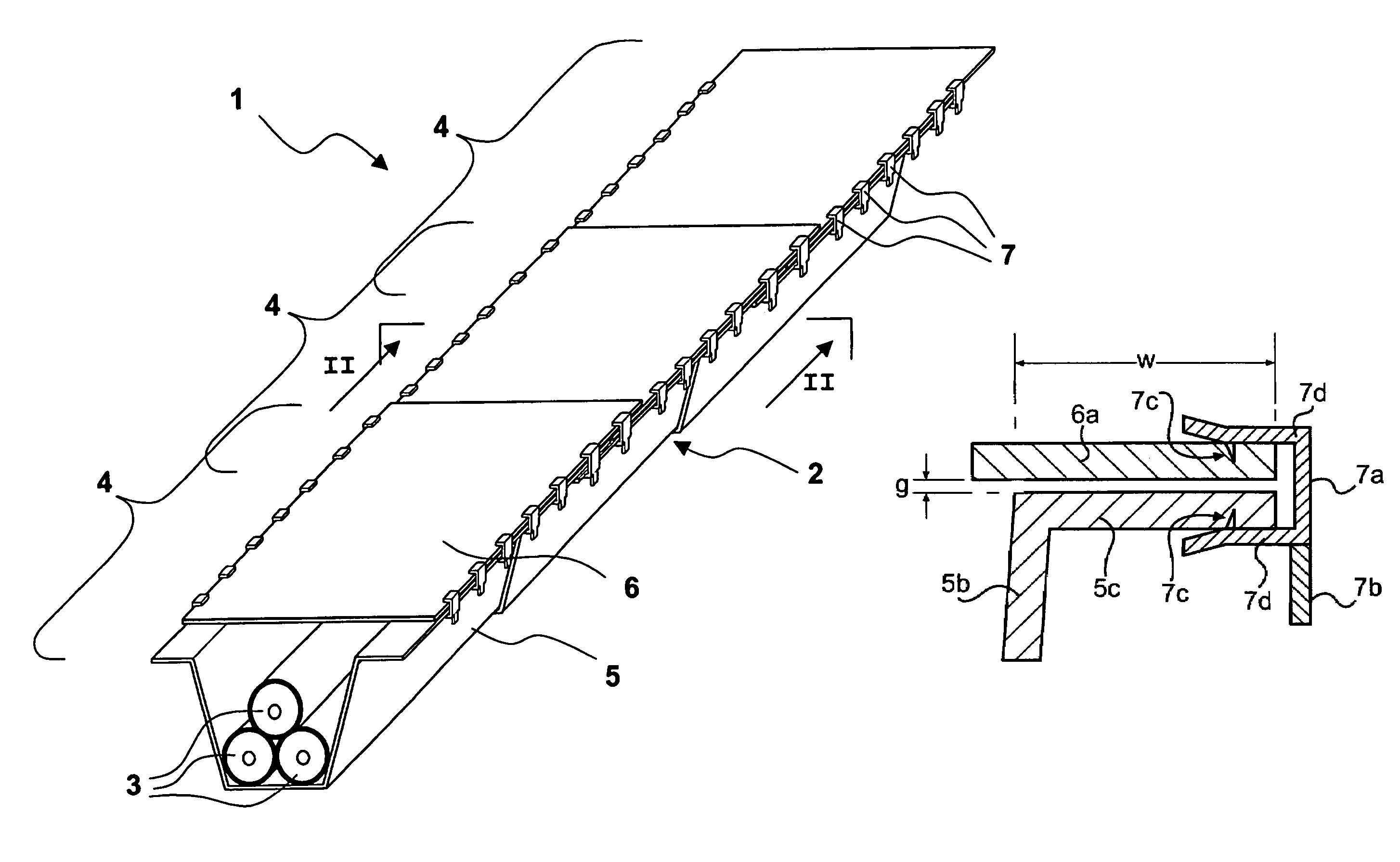
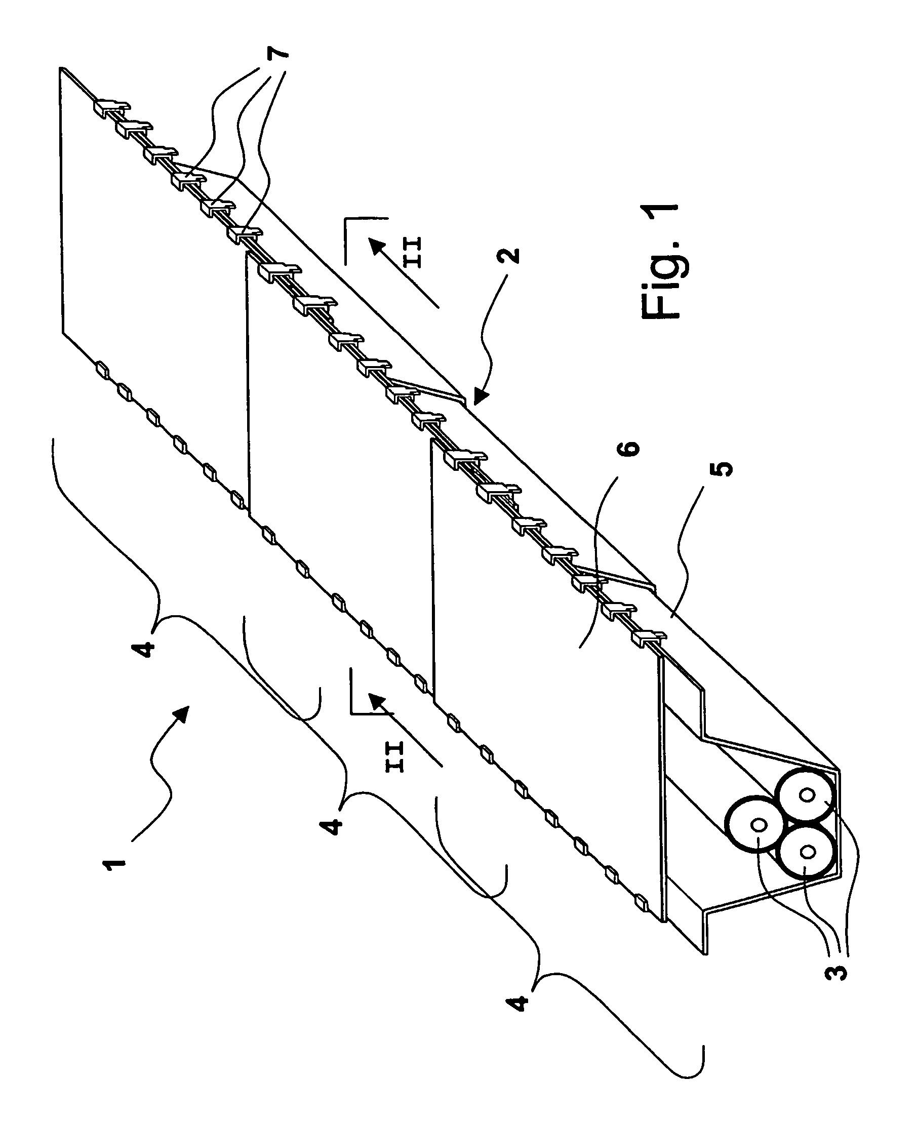
[0087]The test line comprised an electrical current generator, three cables 3 in a trefoil configuration connected to the generator, a cylindrical steel conduit of 50 m length containing the cables 3 from the exit of the generator, and six longitudinal sections 4 containing the cables from the end of the cylindrical conduit. At the exit of the six sections 4, the cables 3 were short-circuited. The longitudinal sections 4 were superimposed for 200 mm and placed 1.4 m underground. The magnetic field was measured by means of a magnetometer model PLM-100WB Handheld ELF produced by MACINTYRE ELECTRONIC DESIGN ASSOCIATES, INC. (485 Spring Park Place, Hemdon, Va. 20170), in a point that is 1 m above ground and between the third and the forth section (i.e. in the middle of the line).

[0088]The dimensions of base member 5 wer...

example 2

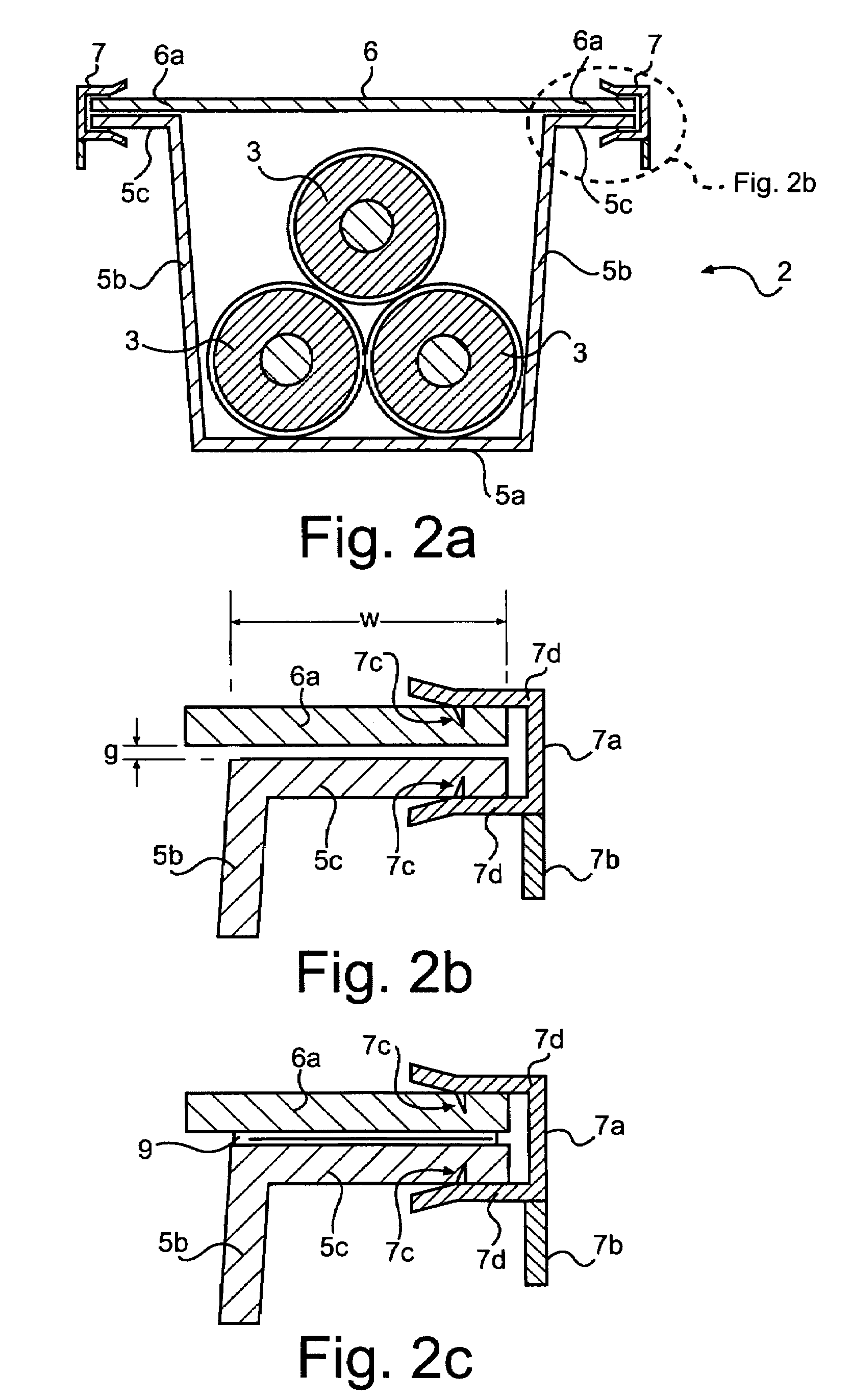
[0106]The Applicant has also determined how the magnetic field varies when the measuring position is changed along a transversal direction (i.e. perpendicular to the conduit direction), at 1 m above ground. Shape, dimensions and material of conduit 2 were as in Example 1, and the following coupling conditions were considered:[0107]a) no coupling and perfect isolation between base 5 and cover 6, achieved by interposing a nylon sheet between base 5 and cover 6;[0108]b) coupling by clips 7 every 50 cm;[0109]c) coupling by clips 7 every 25 cm.

[0110]FIG. 6 shows the results of this experiment. It can be noticed that the curves have a bell-like shape, with the maximum at the point of zero abscissa, i.e. in the median plane of the conduit 2. It can also be appreciated that the percentage improvement obtainable by using clips 7 is substantially constant by moving away from the electrical line 1.

example 3

[0111]The Applicant has performed a new set of measures to compare, by means of an “ad hoc” parameter, the effectiveness of different shielding solutions. Such parameter, herein called “electrical continuity” and identified by the symbol λ, is so expressed:

[0112]λ=100·Bn-BiBn

[0113]wherein Bn is the maximum magnetic field measured 1 m above ground (by means of the same instrument of the first example) under total electrical isolation between base 5 and cover 6, achieved by interposing a nylon sheet between base 5 and cover 6, and Bi is the maximum magnetic field measured 1 m above ground under the particular operating conditions. Parameter λ is independent on the measuring distance and it is therefore an absolute index of the increase of the electrical continuity with respect to the perfect isolation condition. Parameter λ is however dependent on the characteristics of the conduit material, in particular on the magnetic permeability.

[0114]Parameter λ has been measured in the followin...


PUM


Abstract

An electrical power transmission line having at least one electrical cable, a conduit of ferromagnetic material enclosing the electrical cable and having a base and a cover and electrical contact elements for electrically connecting the base and the cover, wherein the electrical contact elements are metal fusion joints or metal resilient members suitable to pierce the ferromagnetic material.

Description

CROSS REFERENCE TO RELATED APPLICATION[0001]This application is a national phase application based on PCT / EP2002 / 011302, filed Oct. 9, 2002, the content of which is incorporated herein by reference.BACKGROUND OF THE INVENTION[0002]1. Field of the Invention[0003]The present invention relates to a method for screening the magnetic field generated by an electrical power transmission line and to an electrical power transmission line so screened.[0004]2. Description of the Related Art[0005]Generally, a high-power electrical transmission line is designed to operate at medium voltages (typically from 10 to 60 kV) and high voltages (typically higher than 60 kV), and currents of the order of hundreds of amperes (typically from 500 to 2000 A). The electrical power carried in these lines can reach values of the order of hundreds of MVA, typically 400 MVA. Normally, the current carried is an alternating current at low frequency, in other words generally below 400 Hz, and typically at 50-60 Hz. ...

Claims


Application Information

Patent Timeline
IPC IPC(8): H01R4/00H02G9/04
CPCH02G9/02H02G9/04H02G9/065
Inventor DONAZZI, FABRIZIOBORGHI, ENRICOMAIOLI, PAOLOSPREAFICO, SERGIO
Owner PRYSMIAN CAVI E SISTEMI ENERGIA
Why Eureka
Try Eureka