

Zoom lens and image pickup apparatus
a pickup apparatus and zoom lens technology, applied in the direction of optics, instruments, optics, etc., can solve the problem of difficulty in providing a sufficient variable power ratio to the number of lens groups in the configuration, and achieve the effect of wide field angle, high variable power ratio, and thin thickness
- Summary
- Abstract
- Description
- Claims
- Application Information
AI Technical Summary
Benefits of technology
Problems solved by technology
Method used
Image

Examples
embodiment 1
Illustrative Embodiment 1
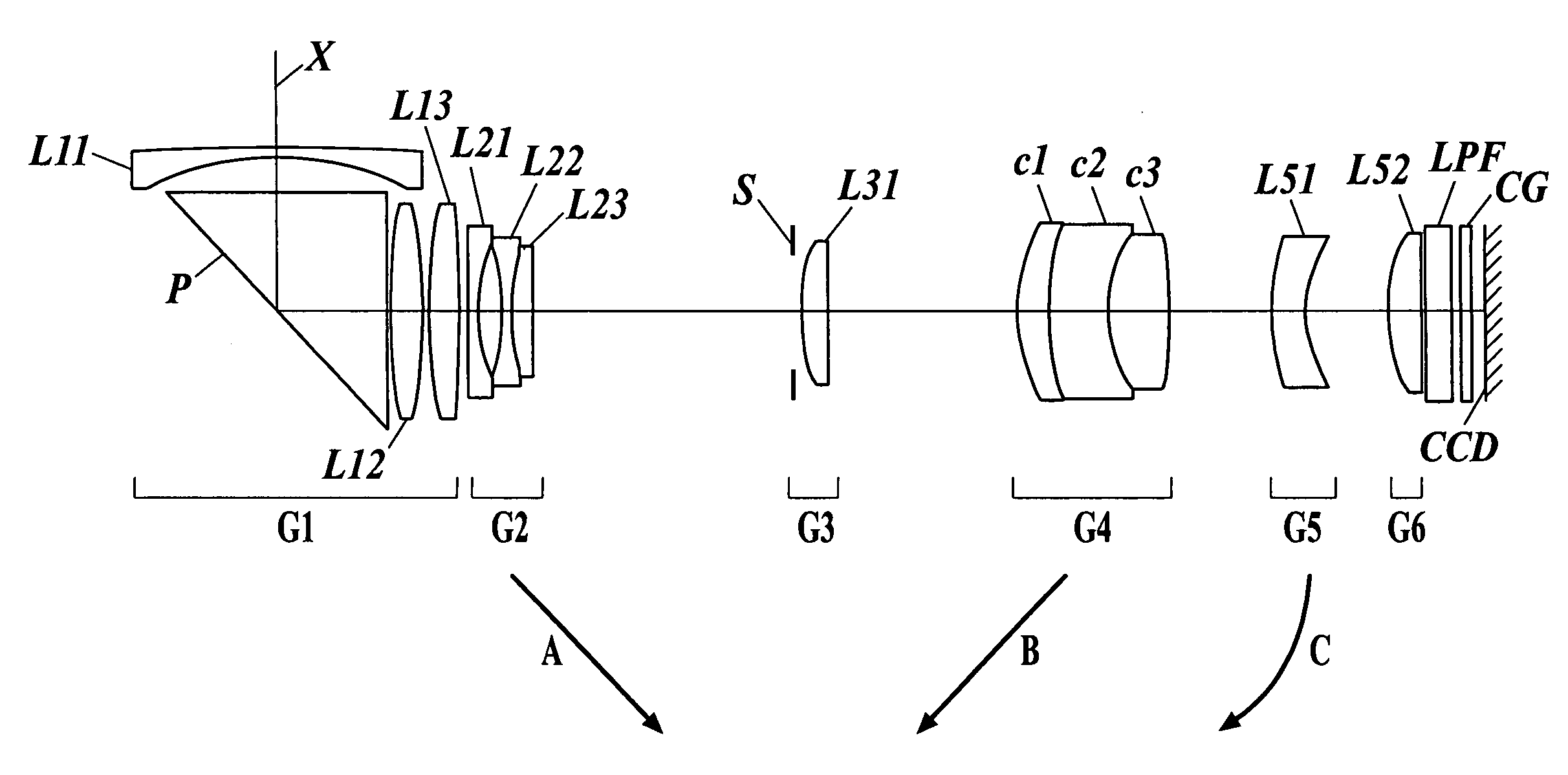
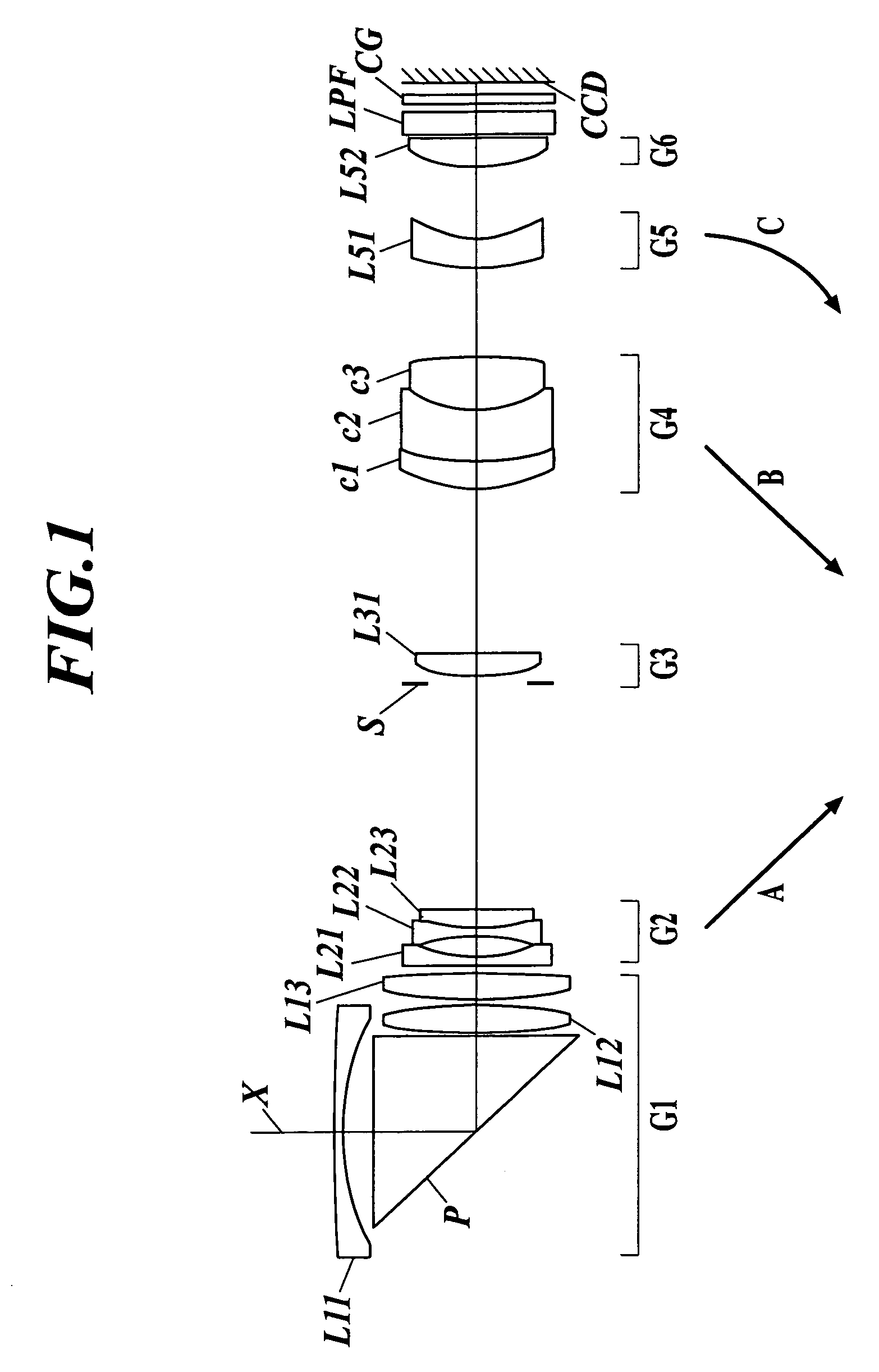
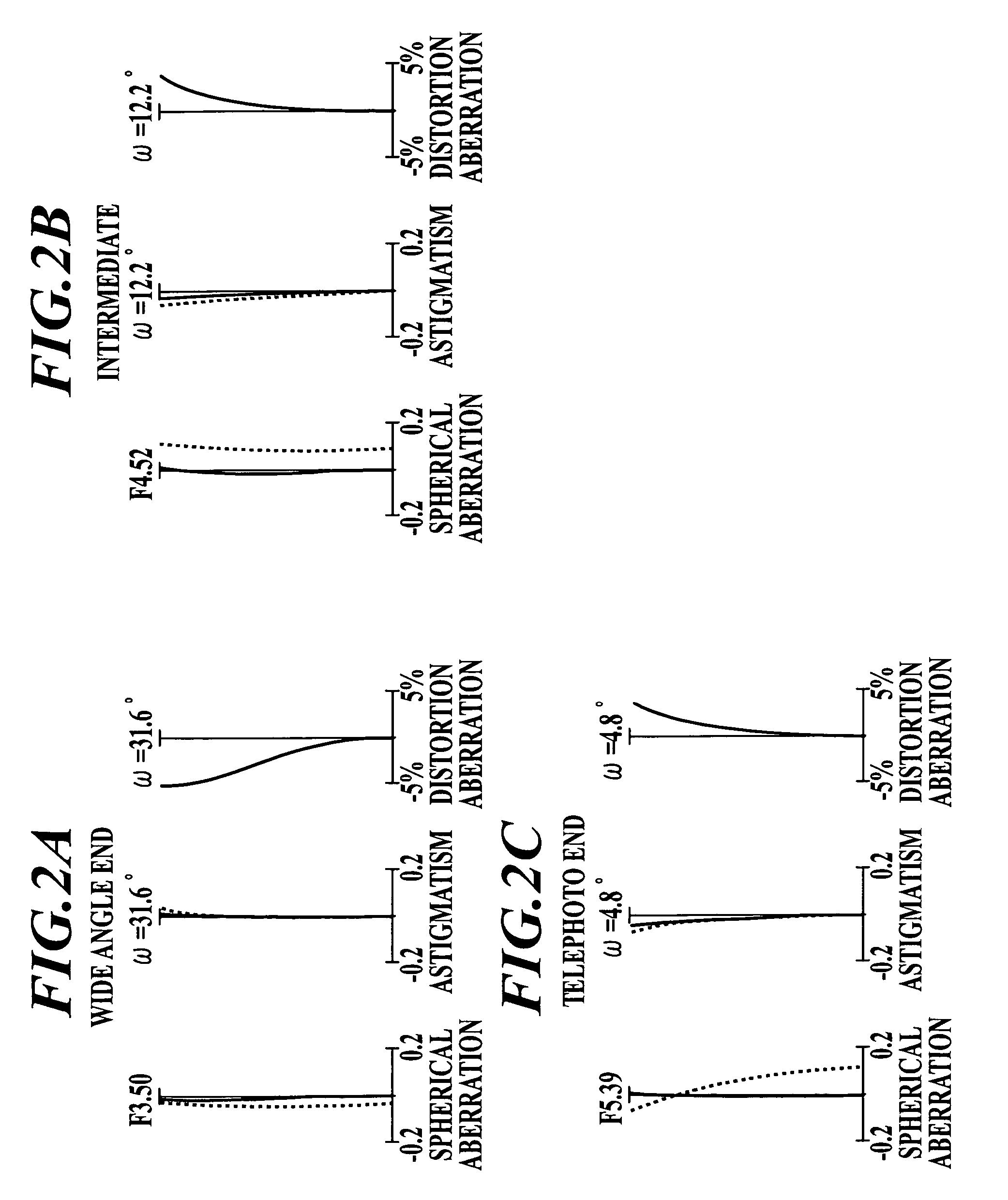
[0203]Table 2 shows lens data for a zoom lens according to Illustrative Embodiment 1. FIG. 1 is a cross-sectional view at a wide angle end of the zoom lens according to Illustrative Embodiment 1. FIGS. 2A to 2C are aberration diagrams illustrating the spherical aberration, astigmatism, and distortion aberration of the zoom lens according to Illustrative Embodiment 1. Here, FIG. 2A is an aberration diagram at a wide angle end. FIG. 2B is an aberration diagram at an intermediate part. FIG. 2C is an aberration diagram at a telephoto end. In the following description, these aberration diagrams will be described based on an assumption that the solid line and the dotted line in the spherical aberration diagram represent the d-line and the g-line, respectively and the solid line and the dotted line in the astigmatism diagram represent a sagittal field and a meridional field, respectively.
[0204]
TABLE 2ILLUSTRATIVE EMBODIMENT 1SURFACE NO.R(mm)d(mm)ndνd 1101.0040.601....
embodiment 2
Illustrative Embodiment 2
[0207]The lens data of the zoom lens of Illustrative Embodiment 2 is shown in Table 3. FIG. 3 is a cross-sectional view at a wide angle end of the zoom lens of Illustrative Embodiment 2. FIGS. 4A to 4C are aberration diagrams illustrating the spherical aberration, astigmatism, and distortion aberration of the zoom lens according to Illustrative Embodiment 2. Here, FIG. 4A is an aberration diagram at a wide angle end. FIG. 4B is an aberration diagram at an intermediate part. FIG. 4C is an aberration diagram at a telephoto end.
[0208]
TABLE 3ILLUSTRATIVE EMBODIMENT 2SURFACE NO.R(mm)d(mm)ndνd 194.0070.601.8466623.8 217.0051.75 3∞12.551.9036631.32 4∞0.20 549.0461.631.4970081.6 6−41.0630.20 728.0351.751.7725049.6 8−61.414d1 (CHANGEABLE) 9−51.5890.551.8340037.2109.7721.4111−11.6980.501.7725049.61215.7751.431.9228620.913−29.690d2 (CHANGEABLE)1413.9131.471.5891361.21558.613d3 (CHANGEABLE)167.9162.261.4970081.61712.5873.151.9228620.9186.3713.121.5831359.419927.306d4 (C...
embodiment 3
Illustrative Embodiment 3
[0211]The lens data of the zoom lens of Illustrative Embodiment 3 is shown in Table 4. FIG. 5 is a cross-sectional view at a wide angle end of the zoom lens of Illustrative Embodiment 3. FIGS. 6A to 6C are aberration diagrams illustrating the spherical aberration, astigmatism, and distortion aberration of the zoom lens according to Illustrative Embodiment 3. Here, FIG. 6A is an aberration diagram at a wide angle end. FIG. 6B is an aberration diagram at an intermediate part. FIG. 6C is an aberration diagram at a telephoto end.
[0212]
TABLE 4ILLUSTRATIVE EMBODIMENT 3SURFACE NO.R(mm)d(mm)ndνd 1130.6950.601.8466623.8 217.7241.98 3∞11.921.9036631.32 4∞0.20 591.8331.871.4970081.6 6−21.6520.20 717.9951.921.7291654.7 8−559.659d1 (CHANGEABLE) 9−59.2820.551.8830040.8109.6741.0811−13.8060.501.7291654.7129.7011.281.9228620.913369.171d2 (CHANGEABLE)1412.6411.481.5831359.41548.845d3 (CHANGEABLE)169.4451.301.4874970.21716.3034.491.8466623.8186.6004.121.5831359.419−27.769d4 (...
PUM
 Abstract
Description
Claims
Application Information