Constant-velocity joint and image-forming device
a constant speed joint and image-forming technology, applied in the direction of electrographic process apparatus, rotary machine parts, instruments, etc., can solve the problems of low quality of image, warping and low quality of final image, etc., to prevent grease leakage, reduce operating noise of constant speed joint, and eliminate the need for grease
- Summary
- Abstract
- Description
- Claims
- Application Information
AI Technical Summary
Benefits of technology
Problems solved by technology
Method used
Image
Examples
first embodiment
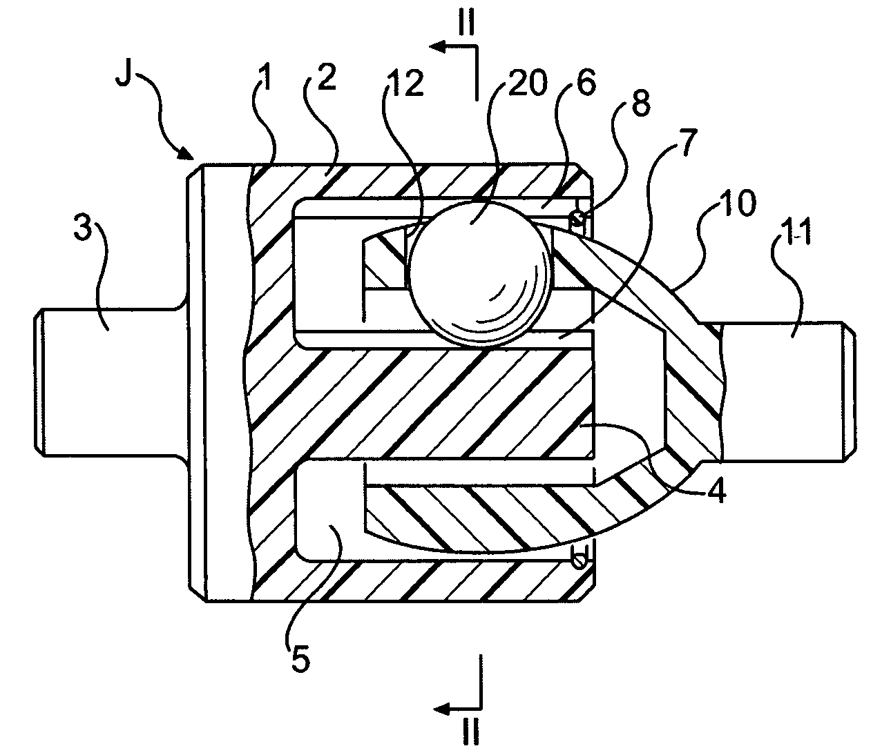
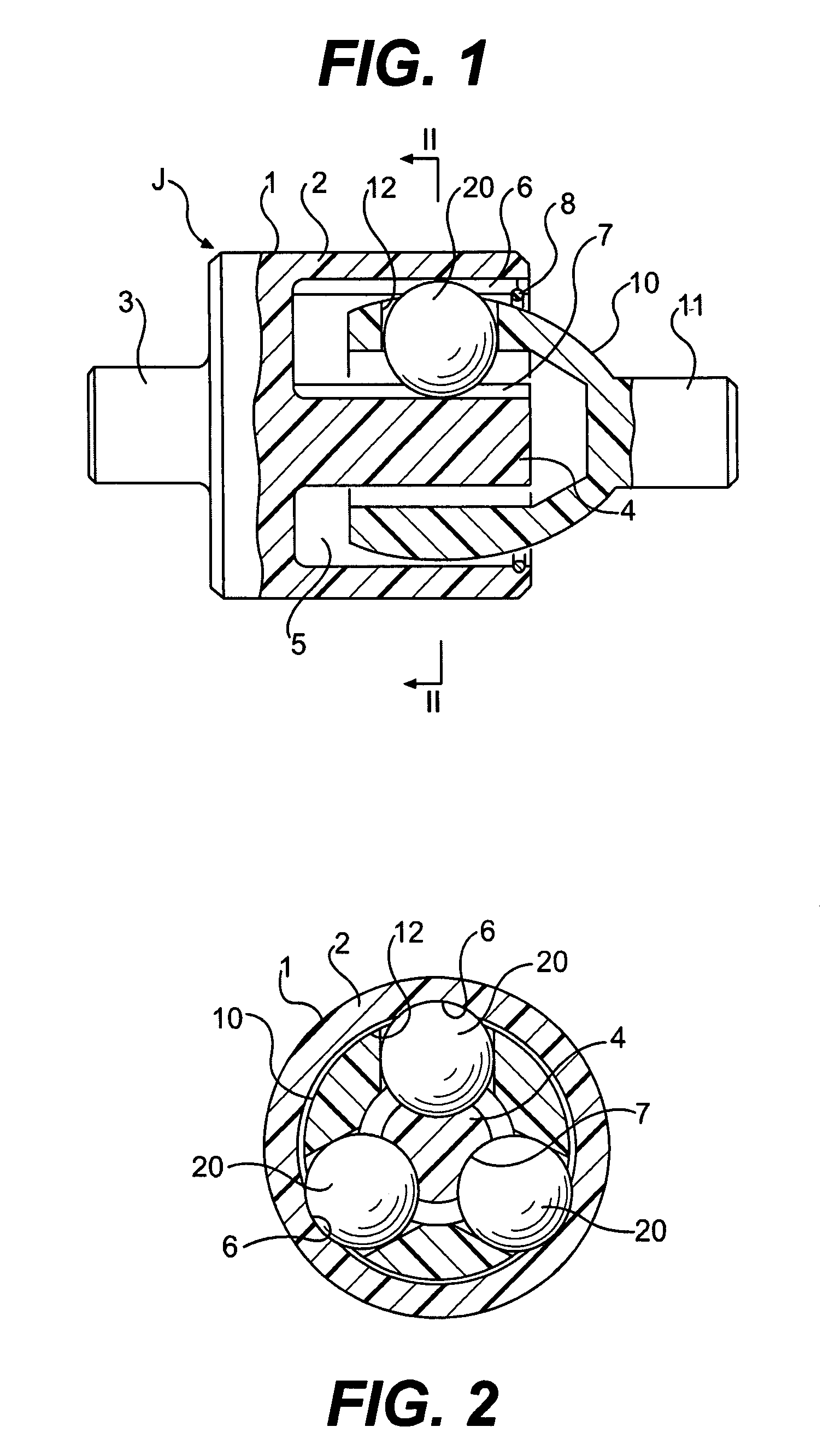
[0033]Now with reference to the drawings, the embodiments of the present invention are described. FIGS. 1 and 2 show the constant-velocity joint according to the present invention. As shown, the constant-velocity joint comprises an outer ring 1, a cage 10 and balls 20.
[0034]The outer ring 1 includes a cup 2 having an opening at one end, and an end wall closing the other end thereof. A first shaft 3 is integrally formed on the outer surface of the end wall of the cup 2. A guide shaft 4 extends from the inner surface of the end wall along the axis of the outer ring 1 to define an annular space between the guide shaft 4 and the cup 2. Three track grooves 6 and three track grooves 7 are formed in the radially inner surface of the cup 2, which defines the radially outer wall of the annular space 5, and in the outer surface of the guide shaft 4, which defines the radially inner wall of the annular space 5, respectively. The track grooves 6 and 7 are circumferentially spaced apart from eac...
second embodiment
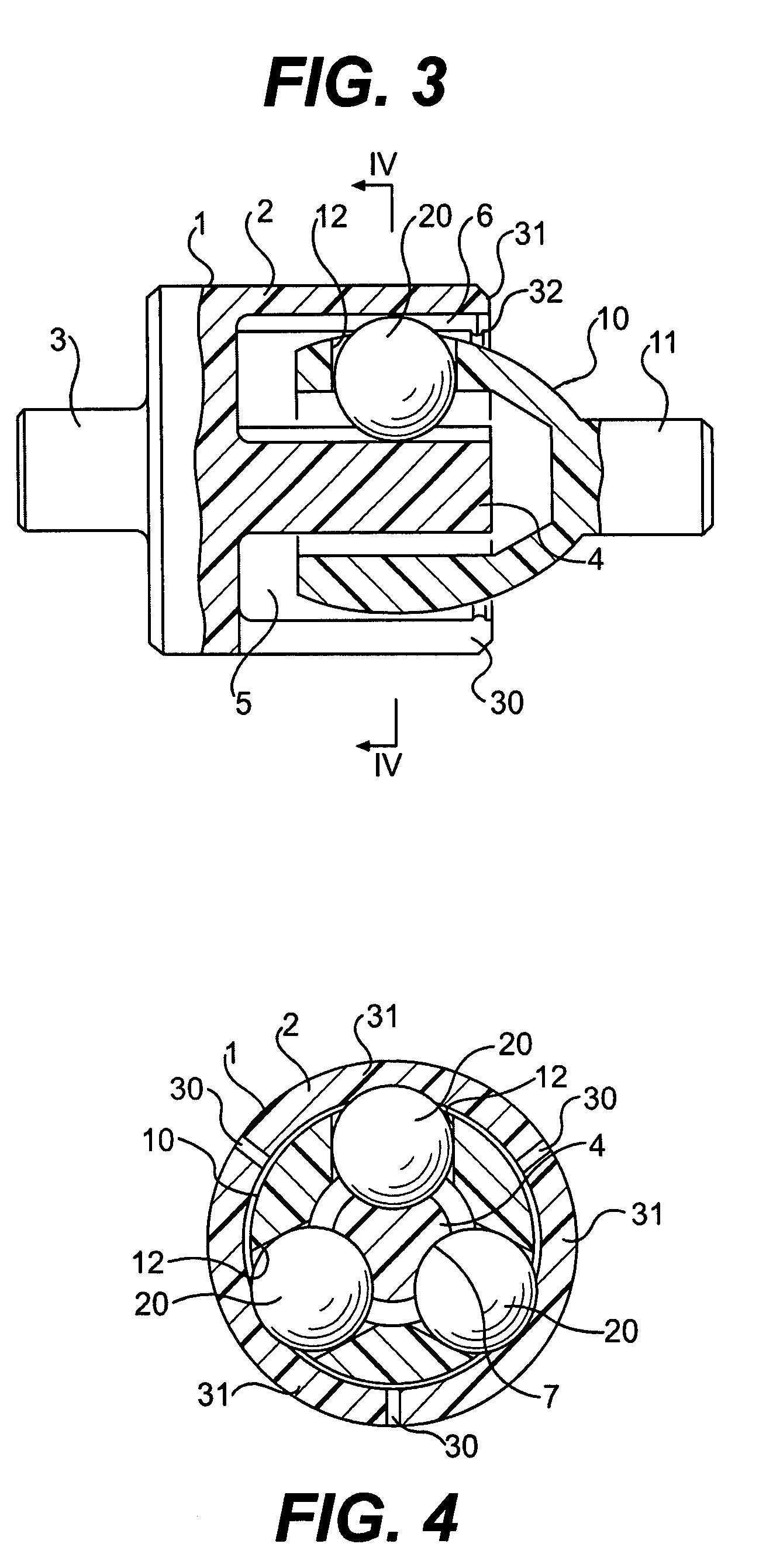
[0060]The constant-velocity joint can thus be easily assembled without using any special tool. No snap ring 8 used in the embodiment of FIG. 1 is necessary, either. The arrangement of the second embodiment thus contributes to a reduction in the number of parts.
[0061]In the second embodiment, if the outer ring 1 is made of a synthetic resin having a high elastic modulus, or if the cup 2 of the outer ring 1 has a sufficient wall thickness, a preload can be applied to the balls 20 from the elastic pieces 31. This allows the constant-velocity joint to operate at a more constant speed with minimum run-out.
[0062]If torque higher than a maximum permissible torque determined by the elastic modulus of the outer ring 1 is applied to the joint, the elastic pieces 31 are allowed to elastically deflect radially outwardly of the cup 2, thereby preventing transmission of torque between the outer ring 1 and the cage 10. The constant-velocity joint thus acts as a torque limiter, too, thereby prevent...
PUM
 Abstract
Description
Claims
Application Information
 - R&D
- Intellectual Property
- Life Sciences
- Materials
- Tech Scout
- Unparalleled Data Quality
- Higher Quality Content
- 60% Fewer Hallucinations
Browse by: Latest US Patents, China's latest patents, Technical Efficacy Thesaurus, Application Domain, Technology Topic, Popular Technical Reports.
© 2025 PatSnap. All rights reserved.Legal|Privacy policy|Modern Slavery Act Transparency Statement|Sitemap|About US| Contact US: help@patsnap.com


