
Distributed control system for forklift

a control system and forklift technology, applied in the field of forklifts, can solve the problems of increasing increasing the number of signal cables, and undesirable increases in the size of the control system, so as to improve the safety of the forklift, improve adaptability and flexibility, and reduce the effect of siz

Inactive Publication Date: 2008-04-29
NISSAN FORKLIFT CO LTD +1
View PDF48 Cites 17 Cited by
  • Summary
  • Abstract
  • Description
  • Claims
  • Application Information

AI Technical Summary

Benefits of technology

[0014]Specifically, an object of the present invention is to provide a distribution control system for improving safety of a forklift.
[0015]Another object of the present invention is to provide a distribution control system for improving adaptability and flexibility.
[0016]Still another object of the present invention is to provide a distribution control system for facilitating the detection of the failure of the controllers, and the determination of the failed location.
[0017]Yet still another object of the present invention is to provide a distribution control system for reducing the size so as to be installed within a size-reduced forklift model.

Problems solved by technology

Recent advance in forklifts components requires control systems to be highly specified, and this leads to increase in the number of signal cables, and also increase in the size of the control systems.
Increase in the size of control systems is undesirable, especially for size-reduced forklifts.

Method used


Image

  • Distributed control system for forklift
  • Distributed control system for forklift
  • Distributed control system for forklift

Examples


Embodiment Construction

[0041]Preferred embodiments of the present invention are described below in detail with reference to the attached drawings.

System Structure

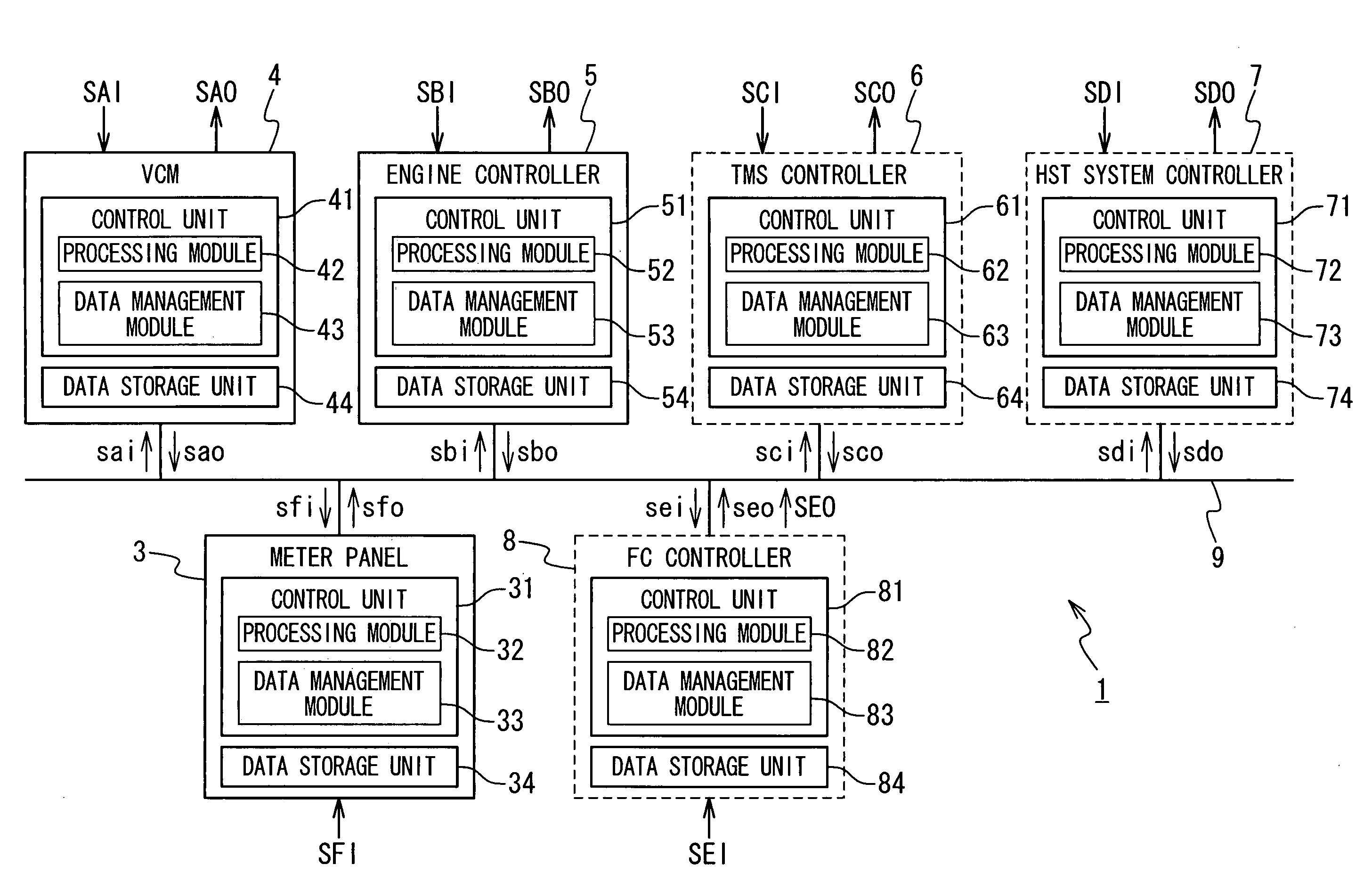
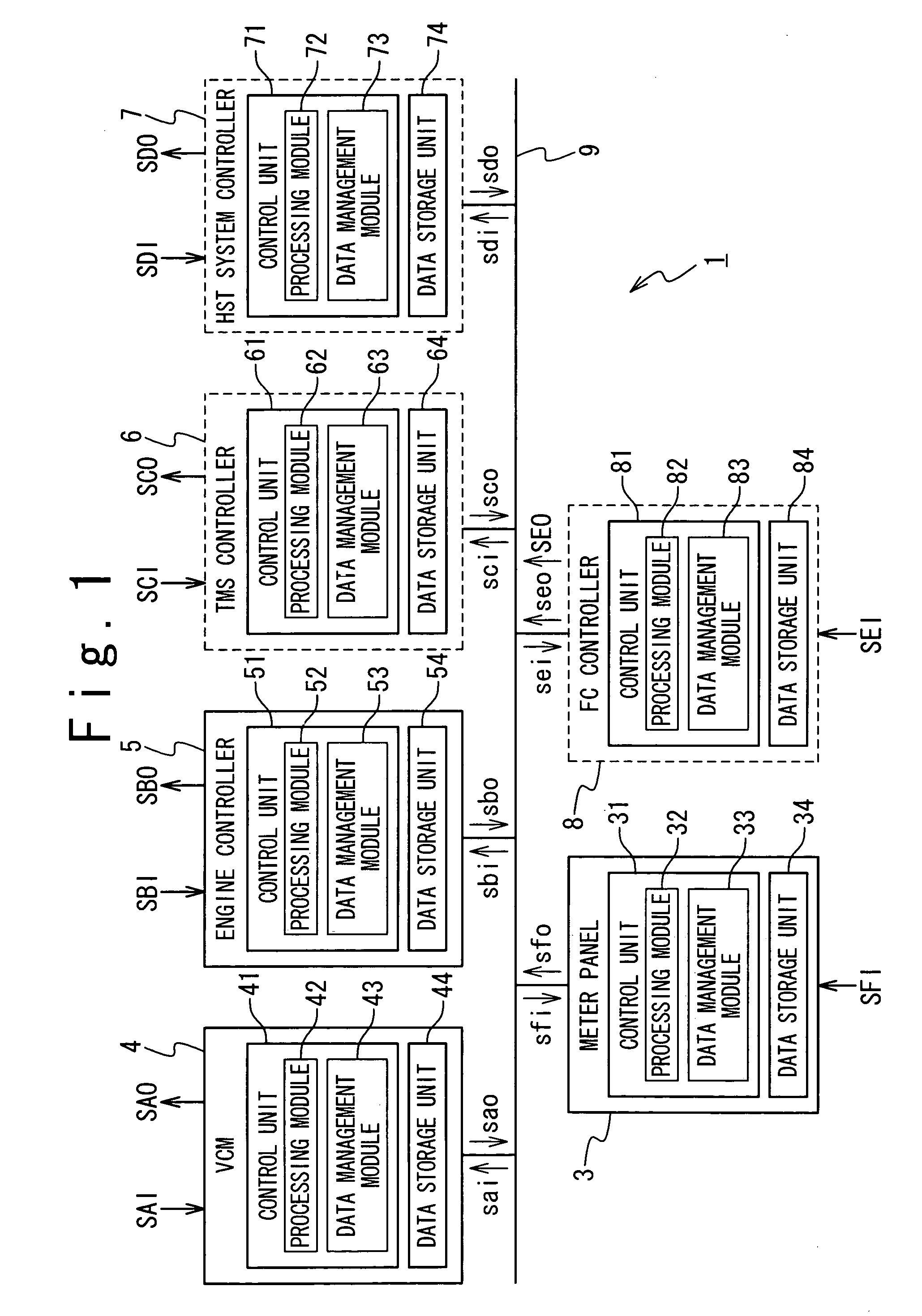
[0042]In one embodiment, as shown in FIG. 1, a distributed control system 1, which is mounted on a forklift with an internal combustion engine (not shown), is configured to control various functions in response to signals received from the forklift components.

[0043]The distributed control system 1 includes a meter panel 3, a vehicle control module (VCM) 4, an engine controller 5, and a CAN (controller area network) bus 9. The vehicle control module 4 provides various functions through controlling various forklift components. The engine controller 5 is a dedicated controller for controlling functions in connection with an engine within the forklift. The CAN bus 9 provides interactive connections among the meter panel 3, the vehicle control module 4, and the engine controller 5, which operate according to the CAN protocol. The CAN protocol is a wel...


PUM


Abstract

A distributed control system including a plurality of controllers mounted on a forklift, and a network providing connections between or among the plurality of controllers within the forklift. A first controller out of the plurality of controllers is configured to control a function in response to an interfacing signal received from a second controller out of the plurality of controllers. When not receiving the interfacing signal during a predetermined period, the first controller controls the function using data stored in the first controller in place of the interfacing signal.

Description

BACKGROUND OF THE INVENTION[0001]1. Field of the Invention[0002]The present invention is generally related to forklifts including distributed control systems, more particularly, to cooperative control using distributed control systems within forklifts.[0003]2. Description of the Related Art[0004]Recently, an increasing number of engine-driven vehicles, including forklifts and construction machines, adopt electronic control systems. Electronic control systems use stored computer programs and control data for controlling respective devices within vehicles.[0005]One requirement of recent forklifts is reduction in size of control systems. Recent advance in forklifts components requires control systems to be highly specified, and this leads to increase in the number of signal cables, and also increase in the size of the control systems. Increase in the size of control systems is undesirable, especially for size-reduced forklifts.[0006]Another requirement is improved flexibility and adapt...

Claims


Application Information

Patent Timeline
IPC IPC(8): G06F19/00F02D29/02G05B19/418B66F9/24G05B23/02
CPCB66F9/24G05B19/418
Inventor OSAKI, KUNIHARUSAITO, TORU
Owner NISSAN FORKLIFT CO LTD
Learn More