Combined laser spirometer motion tracking system for radiotherapy

a motion tracking and laser spirometer technology, applied in radiation therapy, medical science, therapy, etc., can solve the problems of signal drift, difficult to reproduce the same measurements, and significant disadvantages of the late system

Active Publication Date: 2008-05-06
WISCONSIN ALUMNI RES FOUND
View PDF10 Cites 49 Cited by
  • Summary
  • Abstract
  • Description
  • Claims
  • Application Information

AI Technical Summary

Benefits of technology

[0020]Thus it is another object of the invention to provide a range of correction techniques providing for flexible implementation of a correction to the chest displacement signal.
[0021]The model may provide a different functional relationship between chest displacement signal and lung volume during inspiration and exhalation.

Problems solved by technology

Yet, these latter systems have significant disadvantages.
Radiation treatment can extend over many sessions so it is not easy to reproduce the same measurements over the entire course of treatment.
Slight errors in flow measurement accumulate in time and cause signal drift.
When the respiration signal is used for determining precise positioning of tissue for imaging or radiation treatment, set-up sensitivity and drift are significant problems.

Method used


Image

  • Combined laser spirometer motion tracking system for radiotherapy
  • Combined laser spirometer motion tracking system for radiotherapy
  • Combined laser spirometer motion tracking system for radiotherapy

Examples


first embodiment

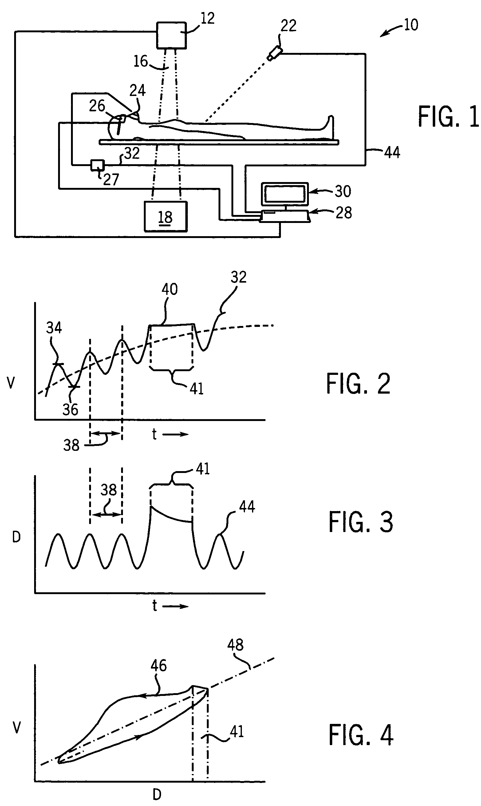
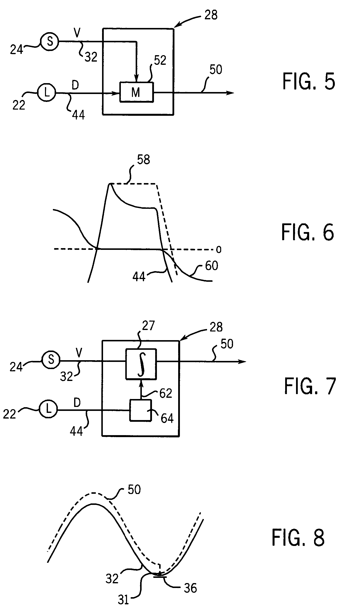
[0061]In a first embodiment, the model 52 receives the lung volume signal 32 and the chest displacement signal 44 to deduce the slope of the slope line 48. The chest displacement signal 44 is then scaled by the slope to translate the chest displacement into units of lung volume but without drift as the corrected respiration signal 50.

[0062]Referring now to FIG. 6, when breath-hold measurements are required, the model 52 may provide for breath-hold-detection to hold corrected respiration signal 50 constant when a breath-hold is detected. In one embodiment, the breath-hold detection may monitor the laser chest displacement signal 44. Breath-hold can be detected from the shape of the chest displacement signal 44 in which the derivative of this signal changes abruptly at the beginning and ending of breath-hold or from spirometer signal 60 in which the flow reading is zero during breath-hold. When a breath-hold is detected, the corrected respiration signal 50 is held to a constant value ...

second embodiment

[0063]In a second embodiment, the correlation curve 46 may be captured as a lookup table fitted to a nonlinear equation and used to map arguments of the chest displacement signal 44 to values of lung volume according to the function captured by the correlation curve 46. By detecting an instantaneous change in the input of the chest displacement signal 44 and using the direction of this change to apply the chest displacement signal to either the upper or lower portion of the correlation curve 46, respectively, a model 52 that accommodates hysteresis can be obtained. The use of correlation curve 46 to convert the chest displacement signal 44 into values of lung volume effectively eliminates the decay artifact in the chest displacement signal 44 because the flat portion of the correlation curve 46 during breath-hold period 41 holds lung volume output constant during the breath-hold period 41. The correlation curve 46 may be an average of a number of breathing periods 38 after baseline ...


PUM


Abstract

An improved non-invasive respiration monitor combines signals from a spirometer and laser chest displacement sensor to reduce signal error. The improved respirations signal can be used for position correction in radiation therapy and imaging applications and can be displayed to a user in breath control techniques.

Description

CROSS-REFERENCE TO RELATED APPLICATIONS[0001]This application claims the benefit of U.S. Provisional application 60 / 478,584 filed Jun. 13, 2003 which is hereby incorporated by reference.STATEMENT REGARDING FEDERALLY SPONSORED RESEARCH OR DEVELOPMENT[0002]This invention was made with United States government support awarded by the following agencies: NIH CA 88960. The United States has certain fights in this invention.BACKGROUND OF THE INVENTION[0003]The present invention relates to respiration sensing equipment and in particular to a respiration sensing device suitable for monitoring respiration during radiation therapy during breath-hold protocols and synchronized breathing protocols.[0004]Accurate monitoring of a patient's breathing can be important in a wide variety of medical applications. In imaging, an accurate knowledge or respiration phase may be used to properly assemble x-ray tomographic or magnetic resonance imaging components acquired during breathing into an image free ...

Claims


Application Information

Patent Timeline
Patent Type & Authority Patents(United States)
IPC IPC(8): A61B5/08A61B5/087A61B5/113A61B6/00A61N5/10
CPCA61B5/1135A61B6/541A61N5/1048A61B5/087A61N5/1037A61N5/1042A61N5/1049A61N5/1064A61N5/1067
Inventor ZHANG, TIEZHIKELLER, HARALDPALIWAL, BHUDATT R.
Owner WISCONSIN ALUMNI RES FOUND
Why Eureka
Try Eureka