Load-invariant amplifier

a technology of variable amplifiers and amplifiers, applied in the direction of amplifiers, push-pull amplifiers, electric devices, etc., can solve the problems of distortion reduction, and achieve the effects of reducing distortion, improving stability, and reducing output impedance of push-pull amplifiers

Inactive Publication Date: 2008-05-06
SANDQUIST PETER
View PDF8 Cites 13 Cited by
  • Summary
  • Abstract
  • Description
  • Claims
  • Application Information

AI Technical Summary

Benefits of technology

[0046]Through the invention, output impedance of a push-pull amplifier decreases because of the absence of degeneration resistors relating to the active output devices. Current sensing for sensing of a current conducted through the output stage sourcing circuitry and a current through the output stage sinking-circuitry is unobtrusive with respect to current delivery to the load since voltages across current sense resistors do not affect output stage control signals in a local feedback fashion. Moreover, distortion decreases since a substantially constant quiescent current is conducted through sinking and sourcing active output devices irrespective of the presence or absence of a large load current. Furthermore, stability is improved because less global voltage feedback is required for a given output impedance or distortion level.

Problems solved by technology

Moreover, distortion decreases since a substantially constant quiescent current is conducted through sinking and sourcing active output devices irrespective of the presence or absence of a large load current.

Method used


Image

  • Load-invariant amplifier
  • Load-invariant amplifier
  • Load-invariant amplifier

Examples


Embodiment Construction

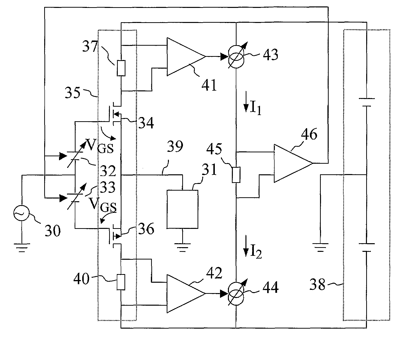
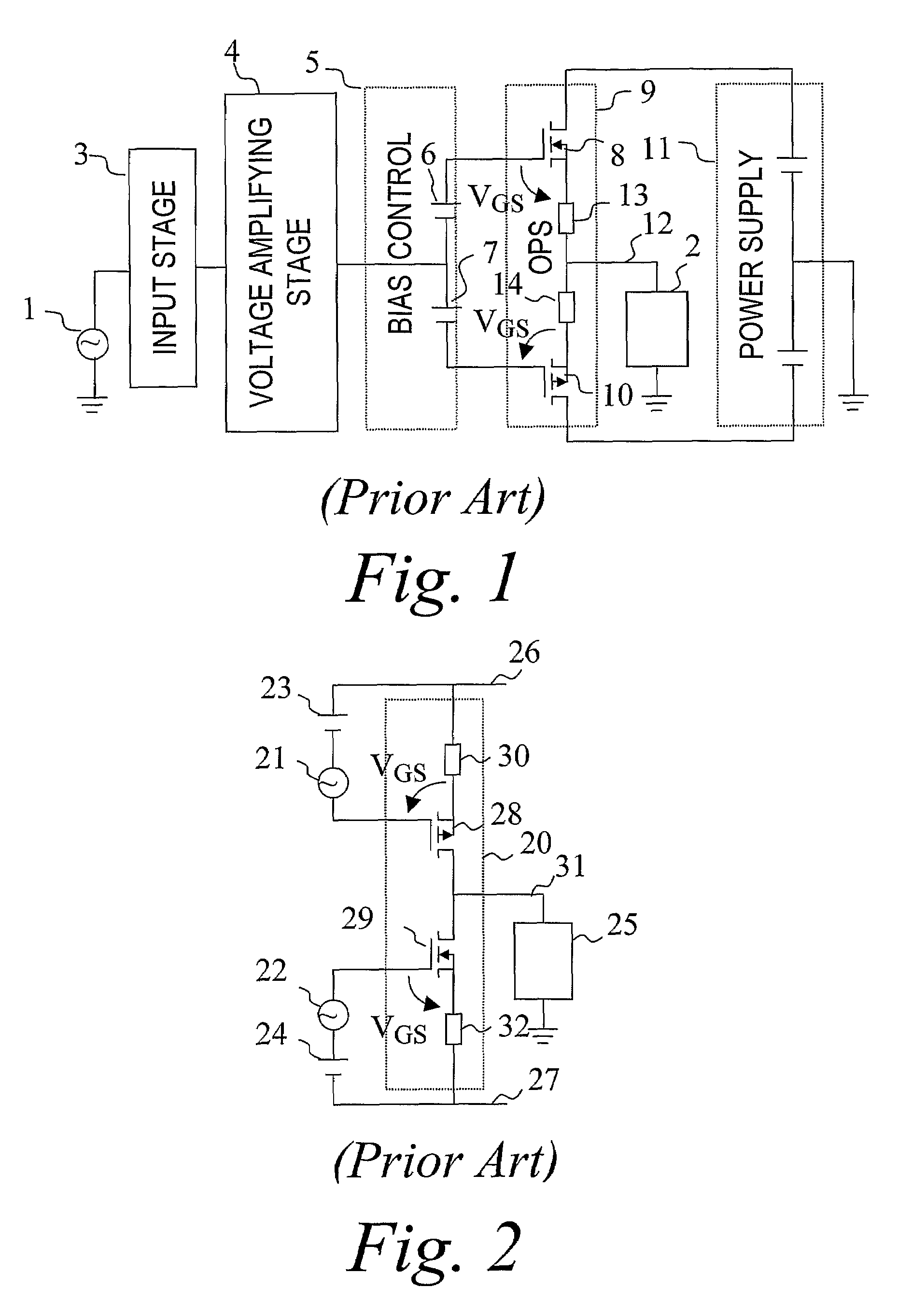
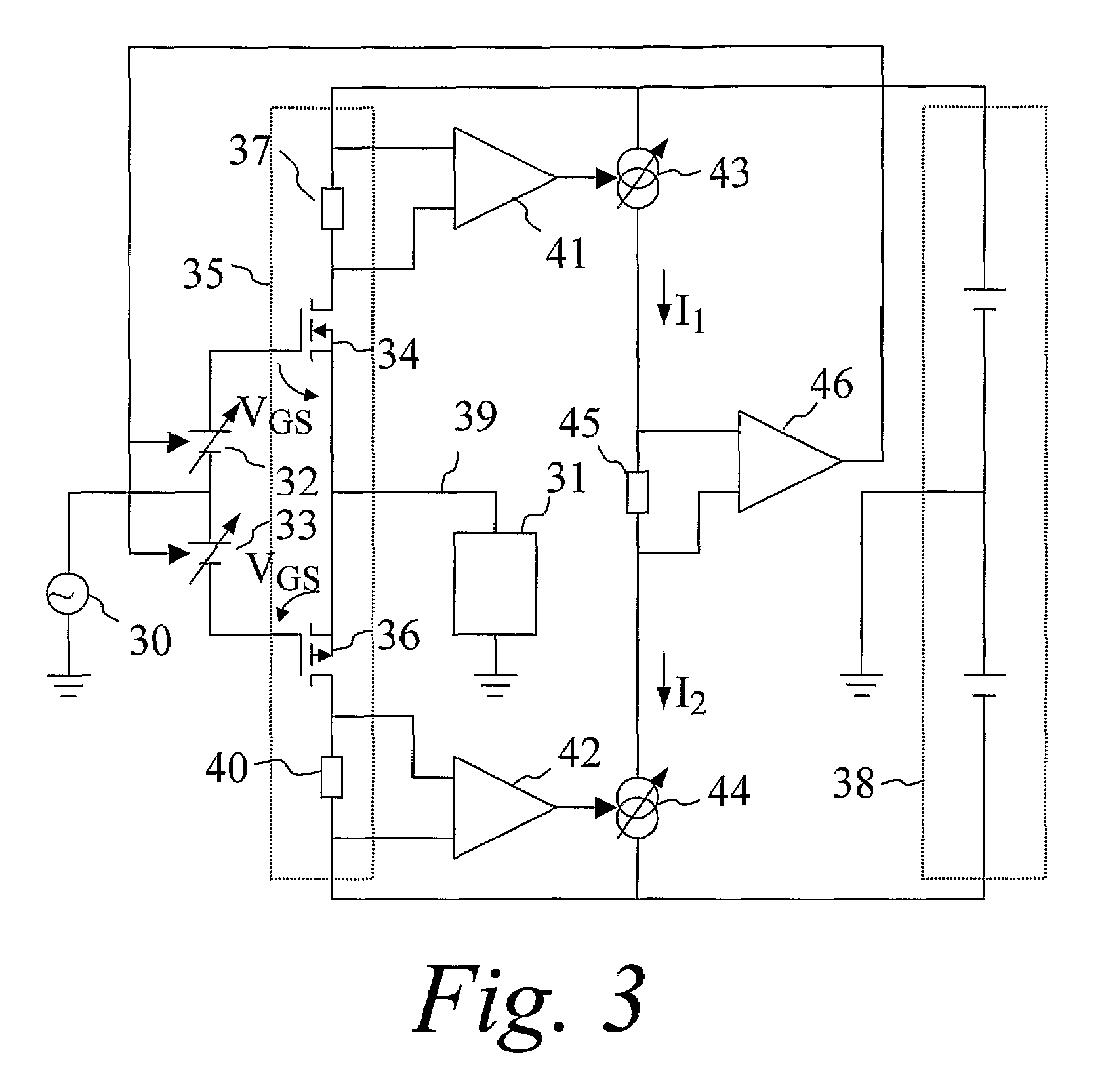
[0054]The invention will now be described in more detail. The invention is applicable to push-pull type power amplifiers generally having an input amplifying stage, intermediate amplifying stages and an Output Power amplifying Stage (OPS). The output stage has power amplifying active output devices. These are typically Bipolar Junction Transistors (BJTs) or Field Effect Transistors (FETs), but may also be valves, Insulated Gate Bipolar Transistors (IGBTs) or perhaps other exotic amplifying devices. Henceforth, these will be referred to simply as active output devices. Power amplifying active output devices being BJTs or FETs will be denoted output transistors.

[0055]In its simplest form, a push-pull type OPS has a sourcing active output device that sources current from a positive terminal of a power supply, and a sinking active output device that sinks current to a negative terminal of the power supply. The terminals of the power supply are substantially voltage sources.

[0056]There a...


PUM


Abstract

A push-pull amplifier having low output impedance and low crossover distortion is provided. A least one of a current through a sourcing current path of an output stage and a current through a sinking current path of the output stage is determinative of a quiescent current control signal produced for controlling a quiescent current of the amplifier. The quiescent current is controlled by symmetrically controlling a bias voltage applied to a sourcing active output device and a bias voltage applied to a sinking active output device in response to the quiescent current control signal. An output stage sourcing control signal for controlling the sourcing active output device is referenced directly to a shared terminal of the sourcing active output device, and an output stage sinking control signal for controlling the sinking active output device is referenced directly to a shared terminal of the sinking active output device.

Description

TECHNICAL AREA [0001]The present invention relates to electronic amplification. More specifically, the invention relates to biasing of linear push-pull power amplifiers.BACKGROUND ART [0002]Electronic amplifiers have found their way into applications such as e.g. audio reproduction. Audio may be represented by a low-level electrical signal. In the process of transforming such a signal into sounds perceivable by the human ear, it is amplified in terms of voltage and / or current and forwarded to an electromechanical transducer, i.e. a loudspeaker. Electrical amplification is accomplished by using a so-called power amplifier.[0003]The vast majority of power amplifiers today for linear applications such as audio reproduction are push-pull amplifiers. Such amplifiers employ disparate first and second circuitry for sourcing and sinking current respectively to a load such as a loudspeaker. Henceforth, the first circuitry will be referred to as sourcing circuitry, and the second circuitry wi...

Claims


Application Information

Patent Timeline
Patent Type & Authority Patents(United States)
IPC IPC(8): H03F3/18H03FH03F1/32H03F3/30
CPCH03F1/3217H03F3/3008H03F3/3016
Inventor SANDQUIST, PETER
Owner SANDQUIST PETER
Why Eureka
Try Eureka