Motorcycle electronic key system
a technology of electronic keys and motorcycles, applied in the field of electronic keys, to achieve the effect of improving the operability of actuation
- Summary
- Abstract
- Description
- Claims
- Application Information
AI Technical Summary
Benefits of technology
Problems solved by technology
Method used
Image

Examples
first embodiment
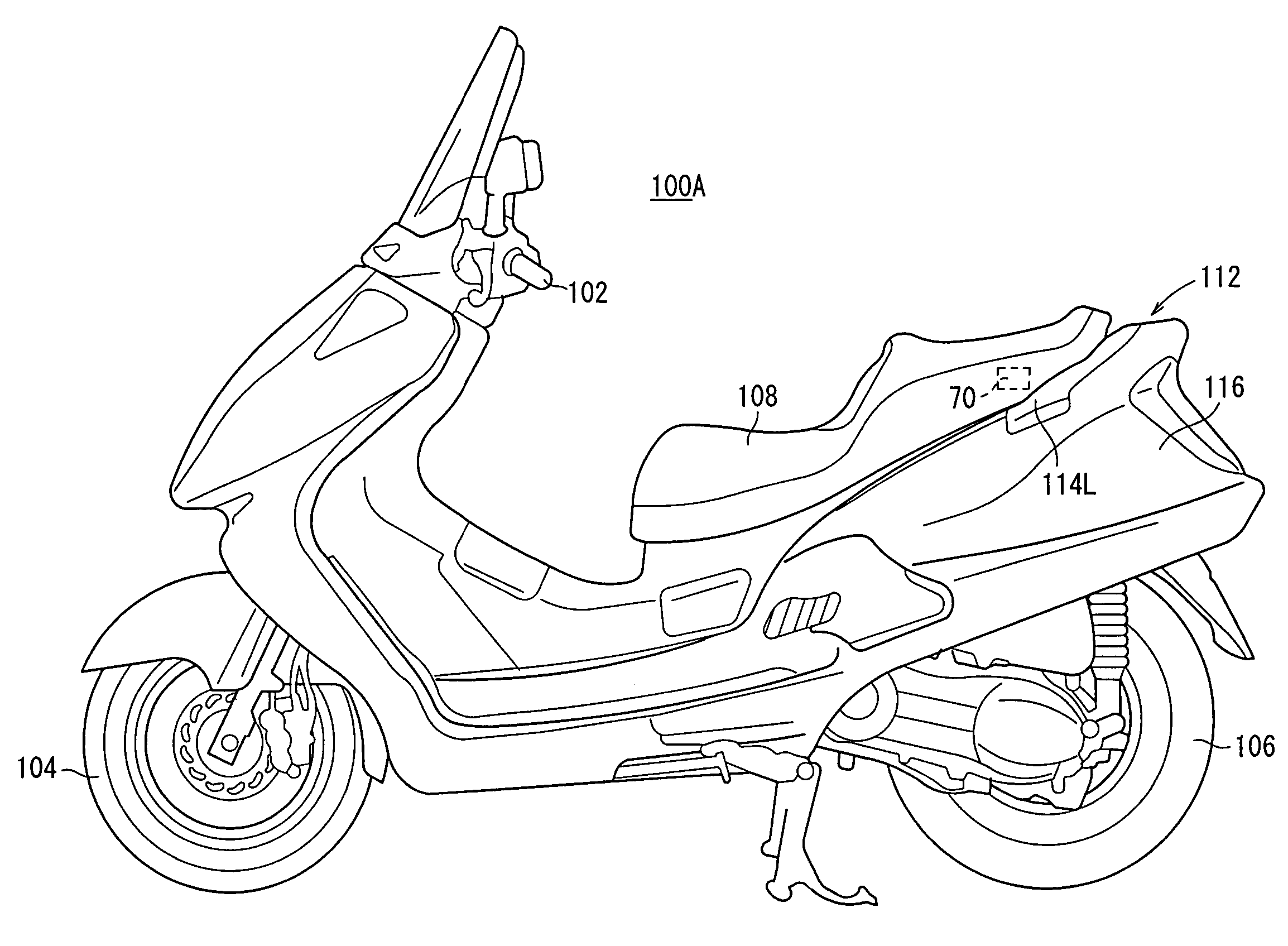
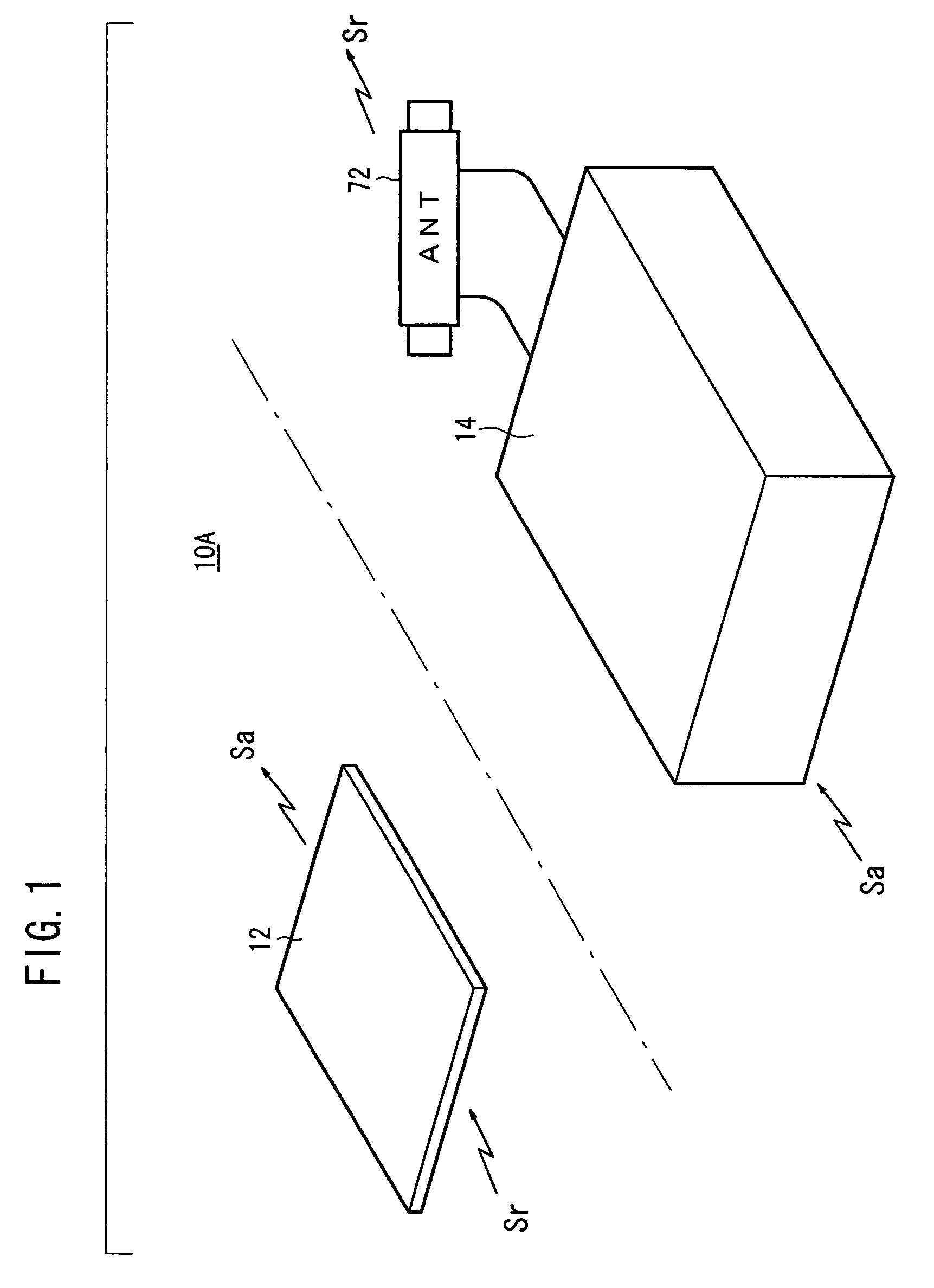
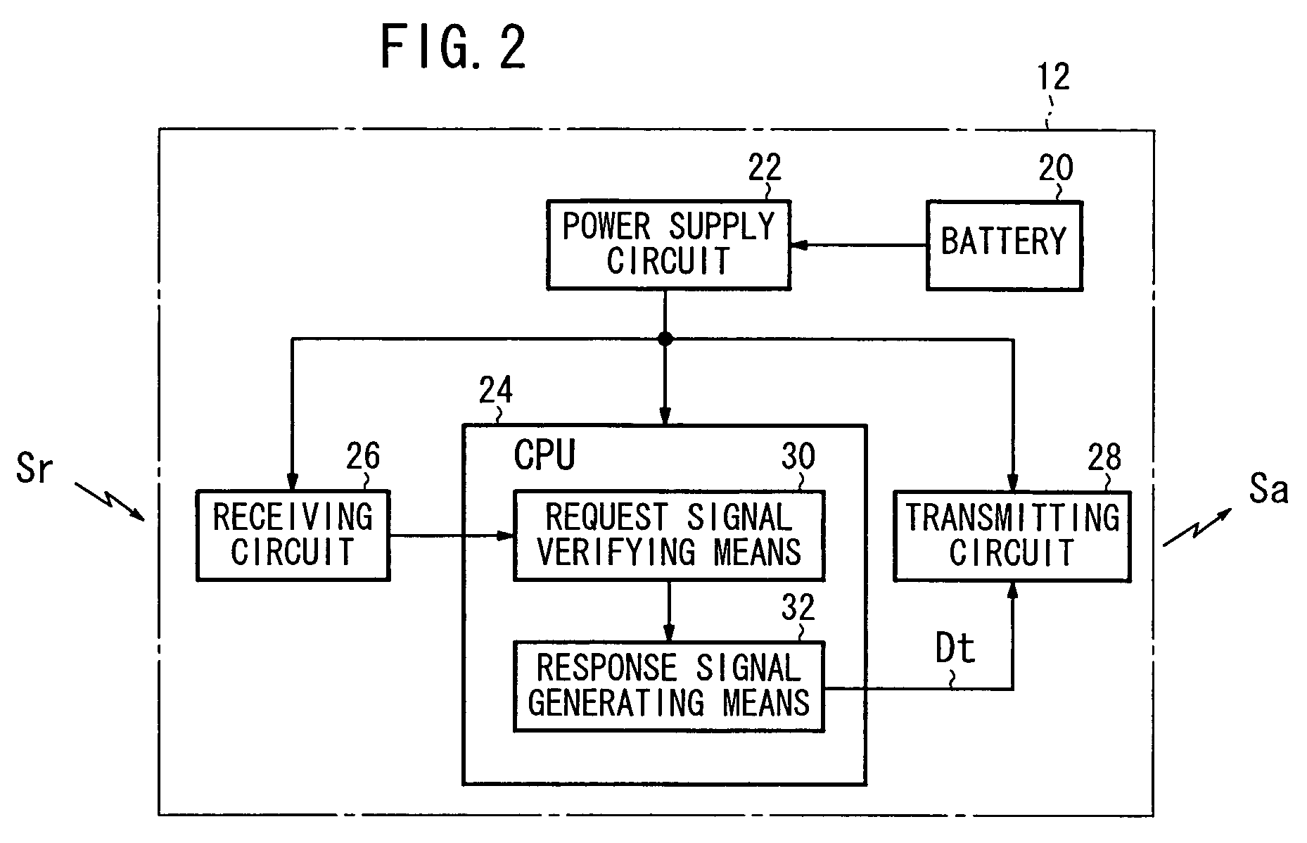
[0039]An electronic key system 10A includes, as shown in FIG. 1, a mobile transmitter-receiver 12 that a user carries, and a control unit 14 mounted to a specific vehicle 100A (See FIG. 4) or a specific vehicle 100B (See FIG. 7). The mobile transmitter-receiver 12 may be formed in a key-shape and including an IC chip integrated therein, or alternatively, may be formed in a card-shape and including an IC chip integrated therein. However, when it is applied mainly as a keyless system, a card-shape is employed. In this embodiment, the mobile transmitter-receiver 12 of a card-shape is assumed for purposes of the present description. Since the mobile transmitter-receiver 12 may be referred to as an electronic key, the mobile transmitter-receiver is referred to as electronic key 12 in the description below.
[0040]The electronic key 12 has a card-shape as described above and, as shown in FIG. 2, includes a battery 20, a power supply circuit 22, a CPU 24, a receiving circuit 26, and a trans...
second embodiment
[0082]Subsequently, referring to FIG. 12 and FIG. 13, an electric key system 10B will be described. Members or units corresponding to FIG. 2 and FIG. 3 are represented by the same reference numerals and will not be described again.
[0083]An electronic key 12 of the electronic key system 10B according to the second embodiment is, as shown in FIG. 12, constructed in almost the same manner as the electronic key 12 according to the first embodiment (See FIG. 2), but differs in that an operating switch 150 is provided.
[0084]A CPU 24 performs at least one step (a request signal generating routine 152). The request signal generating routine 152 is activated based on the turning ON operation of the operating switch 150. The request signal generating routine 152 reads ID data stored in a ROM, not shown, adds an attribute indicating response to the ID data, and outputs it to a transmitting circuit 28 as transmitting data Dt. The transmitting circuit 28, which includes a transmitting antenna, ...
third embodiment
[0097]Referring now to FIG. 14, an electronic key system 10C will be described. The members and units corresponding to FIG. 13 will be represented by the same reference numerals and will not be described again.
[0098]An electronic key 12 used in an electronic key system 10C according to a third embodiment is the same as an electronic key 12 according to a second embodiment described above (See FIG. 12).
[0099]A control unit 14 has substantially the same construction as the control unit14 according to a second embodiment (See FIG. 13), but differs in that a turn ON signal So and a turn OFF signal Sf are supplied from a switching control circuit 154.
[0100]In other words, a timer routine 158 outputs a continuation instruction signal Sc to the switching control circuit 154 when a start switch 70 is turned ON, during a period in which a main switch 62 is in ON-state, and during a period from the time point when the main switch 62 is turned OFF to the time point when the timer routine 158 ...
PUM
 Abstract
Description
Claims
Application Information
 - R&D Engineer
- R&D Manager
- IP Professional
- Industry Leading Data Capabilities
- Powerful AI technology
- Patent DNA Extraction
Browse by: Latest US Patents, China's latest patents, Technical Efficacy Thesaurus, Application Domain, Technology Topic.
© 2024 PatSnap. All rights reserved.Legal|Privacy policy|Modern Slavery Act Transparency Statement|Sitemap