Superconducting quantum antenna

a quantum antenna and superconducting technology, applied in the direction of superconducting devices, superconducting magnetic field measurement, antennas, etc., can solve the problems of large induced voltage drop, initial amplification, and severe restriction of the frequency bandwidth within which reception is possible with conventional antennas, so as to achieve the effect of substantially improving the performance of the sqi

Active Publication Date: 2008-05-06
QEST QUANTENELEKTRONISCHE SYST TUBINGEN GMBH
View PDF6 Cites 40 Cited by
  • Summary
  • Abstract
  • Description
  • Claims
  • Application Information

AI Technical Summary

Benefits of technology

[0015]the junctions of the at least three cells can be energized in such a way that a time-variant voltage drops in each case across at least two junctions of a cell, the time average of which voltage does not vanish,
[0087]Particularly at frequencies of less than 1 GHz, it is advantageous to equip the superconducting quantum interference filter with a feedback loop. In this case, the output signal of the superconducting quantum interference filter is fed back to the superconducting quantum interference filter either positively—to increase the sensitivity—or negatively—to stabilize the operating point. In the case of negative feedback, the circuit can be operated in this case such that the operating point on the characteristic of the superconducting quantum interference filter remains constant. In this case, the feedback current or the feedback voltage includes the information of the incident wave.

Problems solved by technology

However, the induced voltage drop is generally so small that it must initially be amplified with the aid of resonance effects.
Owing to the resonance amplification required for achieving an adequate sensitivity, the frequency bandwidth within which reception is possible is severely restricted with conventional antennas.
However, even here the extent of the antenna must be in the region of the wavelength of the electromagnetic wave to be received, and the sensitivity of such antennas is mostly low.
It is true in principle that magnetic loop antennas can be designed with broader bands than electric antennas, but they cannot be used at relatively high frequencies because of the occurrence of inductive effects and because of the skin effect.
Moreover, during conventional operation the impedance of magnetic loop antennas can be adapted to the impedance of conventional electronic circuits only with difficulty, and the efficiency of the antennas is thereby sharply decreased.
A further problem occurs with conventional antenna systems when electromagnetic waves of very low signal strength are to be received.
The input sensitivity of conventional antenna systems is limited in principle by the noise of the preamplifier following the antenna.
Because of their large dimensions, antenna arrays are not suitable, or suitable only in a severely restricted way, for mobile use, in particular, for example in vehicles, ships or aircraft.
Since conventional antenna systems must extract energy from the electromagnetic field in order to process the information contained in the field, the range of transmission antennas is additionally limited in principle by the number of the receivers for a given transmitter power.

Method used


Image

  • Superconducting quantum antenna
  • Superconducting quantum antenna
  • Superconducting quantum antenna

Examples


Embodiment Construction

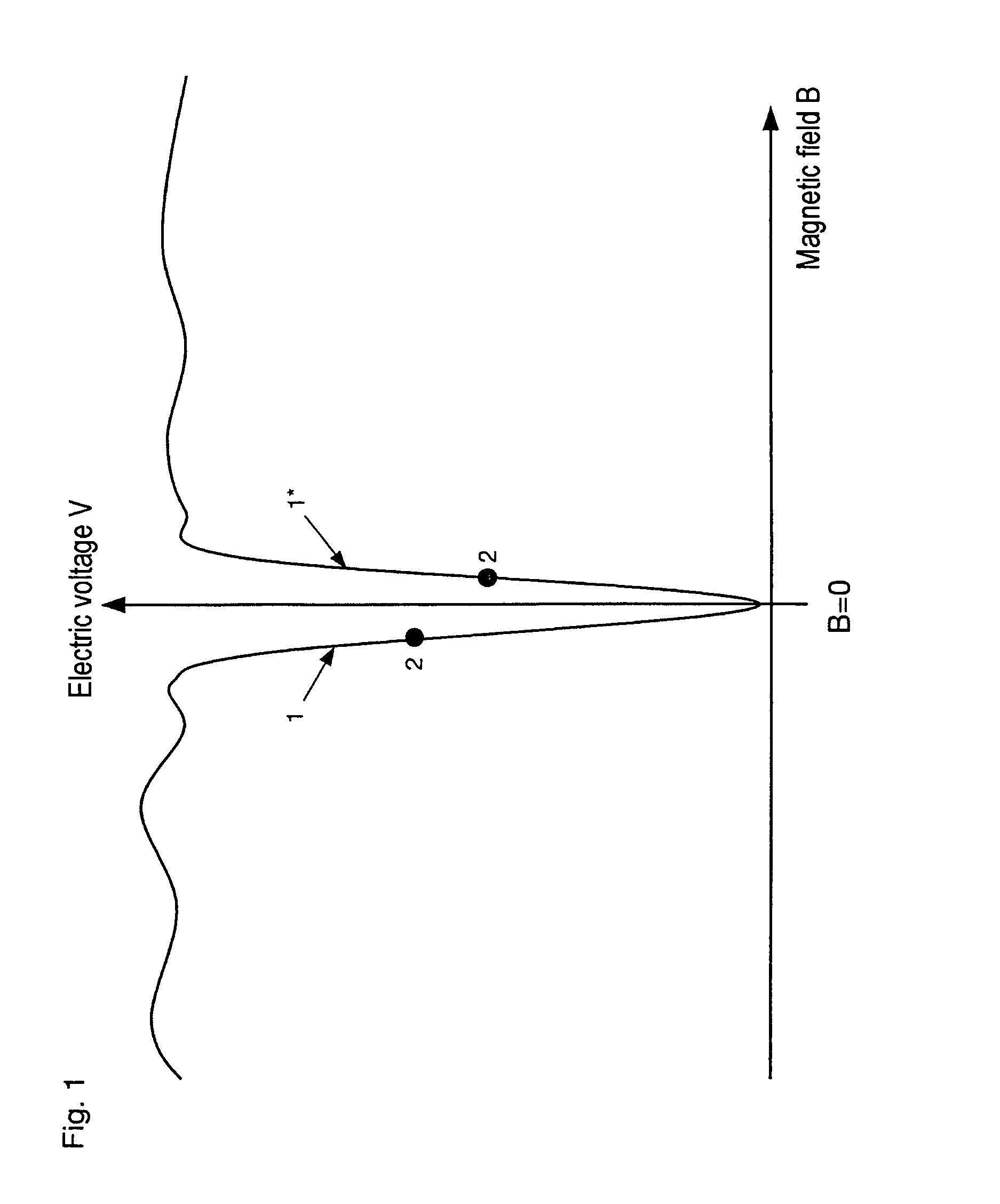
[0138]A typical characteristic of a superconducting quantum interference filter (SQIF) is illustrated in FIG. 1. If the SQIF is supplied with an electric current of suitable strength, a voltage dependent on the magnetic field that permeates the SQIF drops across the SQIF. By contrast with the known, conventional SQUIDs, the characteristic is not periodic, but has an unambiguous minimum in the vanishing magnetic field B=0. Since the characteristic is not sinusoidal, as with the conventional SQUIDs or SQUID arrays, the linearity of its edge 1 or 1* is very high. By setting a suitable operating point 2, something which can be performed, for example, by applying a constant magnetic field (control field), the SQIF can be operated with high linearity as an amplifier or as a current-to-voltage converter.

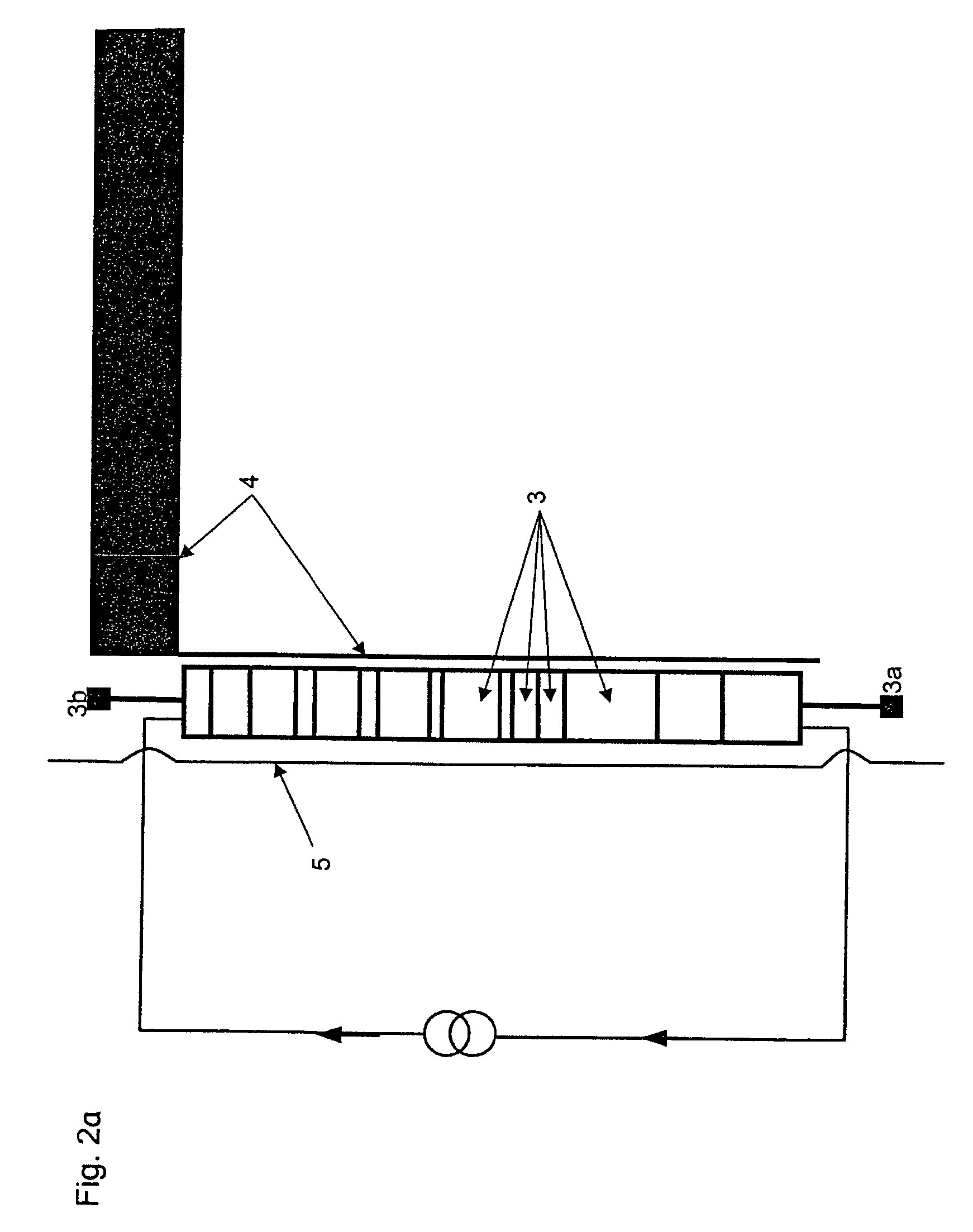
[0139]A typical antenna circuit is illustrated in FIG. 2a. The SQIF 3 is coupled inductively to a primary antenna 4. Upon incidence of an electromagnetic wave, an antenna current flows thro...


PUM


Abstract

An antenna for electromagnetic waves including a quantum interference filter, at least one low-temperature transistor and primary antenna structures, means for deriving an electromagnetic wave from the circuit, cooling elements and insulating means. The interference filter and the transistor act as active components, the primary antenna structure is connected up to at least one of the active components in such a way that upon incidence of an electromagnetic wave on the primary antenna structure there is present at the output of the at least one active component a conducted electromagnetic wave, and wherein at least one part of the circuit and at least one part of the primary antenna structure are thermally insulated, the thermal insulation is frequency transparent to electromagnetic waves, and the cooling elements are designed to cool down at least one part of the circuit below the transition temperature of at least one of the superconducting materials.

Description

CROSS REFERENCE TO RELATED APPLICATIONS[0001]This application is a continuation of International Application No. PCT / DE2004 / 001209 having an international filing date of Jun. 14, 2004, which designated the United States, the entirety of which is incorporated herein by reference.[0002]This application also claims the benefit of German Application No. 103 27 061.2 filed Jun. 13, 2003, the entirety of which is incorporated herein by reference.FIELD OF THE INVENTION[0003]The present invention relates to an active highly sensitive antenna for electromagnetic waves that includes at least one superconducting quantum interference filter or at least one low temperature transistor.BACKGROUND OF THE INVENTION[0004]The mode of operation of conventional electric receiving antennas is based essentially on the fact that an incident electromagnetic wave induces a voltage drop across the antenna that constitutes the input signal for the receiving electronics. However, the induced voltage drop is gen...

Claims


Application Information

Patent Timeline
Patent Type & Authority Patents(United States)
IPC IPC(8): H01Q13/00H01Q1/38H01Q1/42G01R33/035H01Q1/36
CPCG01R33/0358H01Q1/364
Inventor OPPENLANDER, JORGHAUSSLER, CHRISTOPHSCHOPOHL, NILSFRIESCH, ALEXANDERTOMES, JORG
Owner QEST QUANTENELEKTRONISCHE SYST TUBINGEN GMBH
Why Eureka
Try Eureka