Apparatus and method for measuring particulate flow rate

a flow rate and flow rate technology, applied in the direction of liquid/fluent solid measurement, instruments, packaged goods types, etc., can solve the problems of reducing the accuracy of the desired volume of material, wasting expensive additives and feedstocks, and slowing down the system or process in which the device is incorporated, so as to reduce or eliminate the problems associated, the effect of reducing the cost of the process

Active Publication Date: 2008-05-06
ROGERS DONALD SCOTT
View PDF28 Cites 12 Cited by
  • Summary
  • Abstract
  • Description
  • Claims
  • Application Information

AI Technical Summary

Benefits of technology

[0008]A device for measuring the volume of a particulate stream that incorporates a transparent tube and optical sensor as described above is particularly suited for use in particulate material conveying devices, blenders and feeders. One supplier of such devices is Conair, Inc., One Conair Drive, Pittsburgh, Pa. 15202, which manufactures feeders and conveying devices that are used in conjunction with plastic molding and extrusion devices. Many of the currently used material conveying devices employ gravity feeding of the particulate material through a hopper and the control of the rate of flow of the particulate material is problematic and must be adjusted by trial and error in many cases. Additionally, changes made to the downstream process may cause a change in feedstock flow, thus requiring readjustment of additive flow rates. This may result in the imprecise feeding of the particulate material and may result in the wasting of expensive additives and feedstocks, an increase in the cost of the process, a substandard product or any combination of the above. Use of a continuous volume-measuring device as described by Applicant will reduce or eliminate the problems associated with calibrating the flow of particulate material in many particulate delivery devices.

Problems solved by technology

The use of such scales or weight-measuring devices can be expensive and may slow down the system or process in which the device is incorporated.
The use of bushings or similar containers in such systems may limit the ability to precisely control a desired volume of material without the need to change or use multiple containers or bushings.
Changing the containers or bushings may slow down the system or process increasing the cost of operation and decreasing the output of systems incorporating such devices.
Verification of the rate of flow can be expensive, time consuming and imprecise.

Method used


Image

  • Apparatus and method for measuring particulate flow rate
  • Apparatus and method for measuring particulate flow rate

Examples


Embodiment Construction

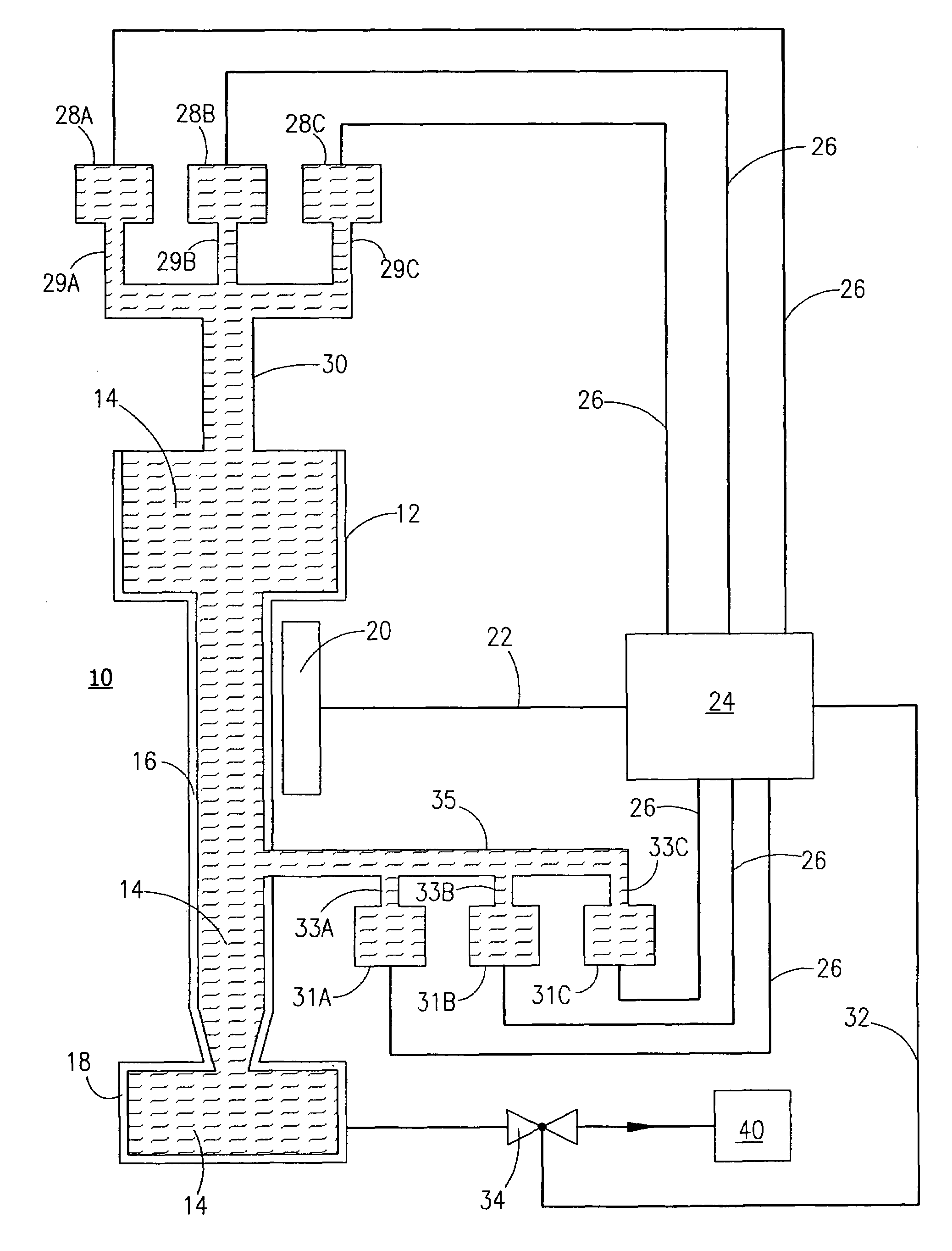
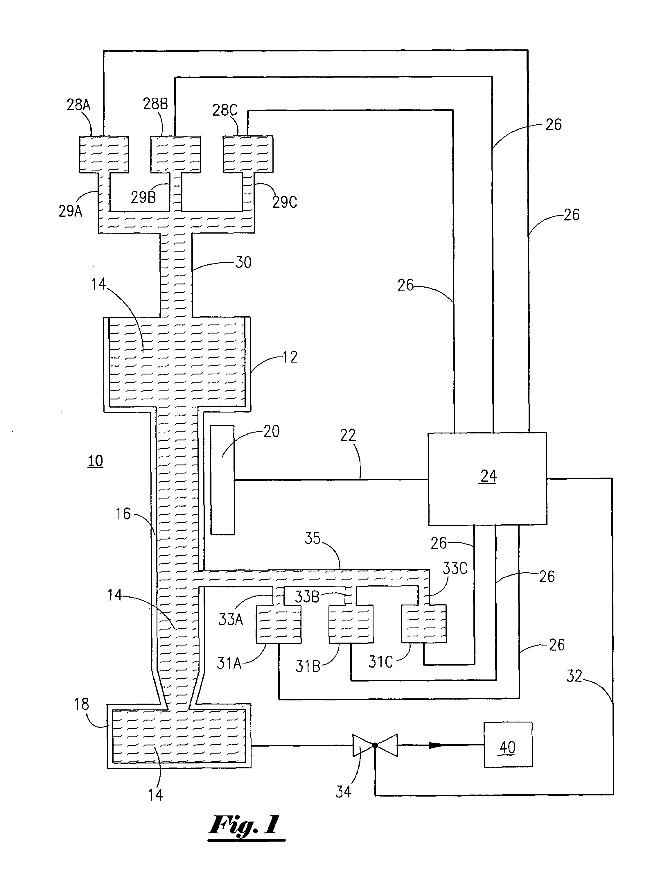
[0011]FIG. 1 shows a schematic of the apparatus for the optical measurement of the volume of a particulate stream of Applicant's invention. The apparatus (10) is comprised of a particulate hopper (12) for retaining a quantity of particulate material (14) delivered from a feedstock supply line (30).

[0012]As further shown in FIG. 1, a transparent tube (16) of a known cross-sectional area is configured to receive a quantity of particulate material (14) flowing from the hopper (12). Flow of the particulate material (14) from the hopper (12) to the transparent tube (16) may be by gravity flow or by other means.

[0013]The flow of the particulate material (14) through the tube (16) is maintained at a rate to produce substantially laminar flow conditions through the tube by means of adjusting the tube geometry to the type of particulate material involved. The intent is to produce a flow of particulate material though the tube with substantially no boundary layer at the tube wall. When such l...


PUM

PropertyMeasurementUnit
volumeaaaaaaaaaa
transparentaaaaaaaaaa
weightaaaaaaaaaa

Abstract

An apparatus for measuring the rate of flow of a volume of particulate material comprising a transparent tube of known cross-sectional area, means for supplying a flow of particulate material through the transparent tube, and an optical signal sensor for receiving an optical signal through the wall of the transparent tube from the flow of particulate material. The received optical signal is delivered to a controller for analyzing and determining the relative movement of the flow of particulate material at the wall of the tube and calculating the rate of volume flow through the tube. These observations may be used to control upstream and downstream system processes and equipment.

Description

FIELD OF THE INVENTION[0001]This invention relates generally to a method for measuring the volume of a flow of particulate material, and more particularly to an apparatus and method of measuring the volume of flow of a particulate feedstock stream by means of an optical sensing device.BACKGROUND OF THE INVENTION[0002]It is desirable in many devices and systems to have a relatively precise measurement of a volume or weight of particulate material. In such devices and systems, scales or other weight-measuring devices are used to weigh a desired amount of particulate material. Containers or bushings of a known volume are also used to measure a desired volume of the particulate matter. Auger or screw conveyors are also employed to supply particulate material at a desired feed or volume rate.[0003]The use of such scales or weight-measuring devices can be expensive and may slow down the system or process in which the device is incorporated. The use of bushings or similar containers in suc...

Claims


Application Information

Patent Timeline
Patent Type & Authority Patents(United States)
IPC IPC(8): G01N21/00G01F1/00
CPCB65B1/30G01F1/708
Inventor ROGERS, DONALD SCOTT
Owner ROGERS DONALD SCOTT
Why Eureka
Try Eureka