Router for virtual private network employing tag switching

Inactive Publication Date: 2008-05-06
CISCO TECH INC
View PDF33 Cites 92 Cited by
  • Summary
  • Abstract
  • Description
  • Claims
  • Application Information

AI Technical Summary

Benefits of technology

[0030]We greatly reduce these problems by a judicious use of packet tagging. PE routers in systems that implement the present invention's teachings still use VPN-specific routing information in making their routing decisions, so they still must maintain tables of such VPN-specific information. But they relieve transit routers of the need to do so. When a PE router receives a packet from a customer enterprise, it provides the packet with an internal-routing field, which a transit router can interpret as specifying the egress PE router that will forward the packet into the remotely located part of the customer-enterprise network. For example, the internal-routing field may include a tag that the transit

Problems solved by technology

To appreciate the resultant improvement, one must recognize that one of the main problems in large IP backbones is the quantity of resources (memory, processing, bandwidth) needed to maintain the routing information.
Clearly, this greatly exacerbates the exi

Method used


Image

  • Router for virtual private network employing tag switching
  • Router for virtual private network employing tag switching
  • Router for virtual private network employing tag switching

Examples


Embodiment Construction

Overview

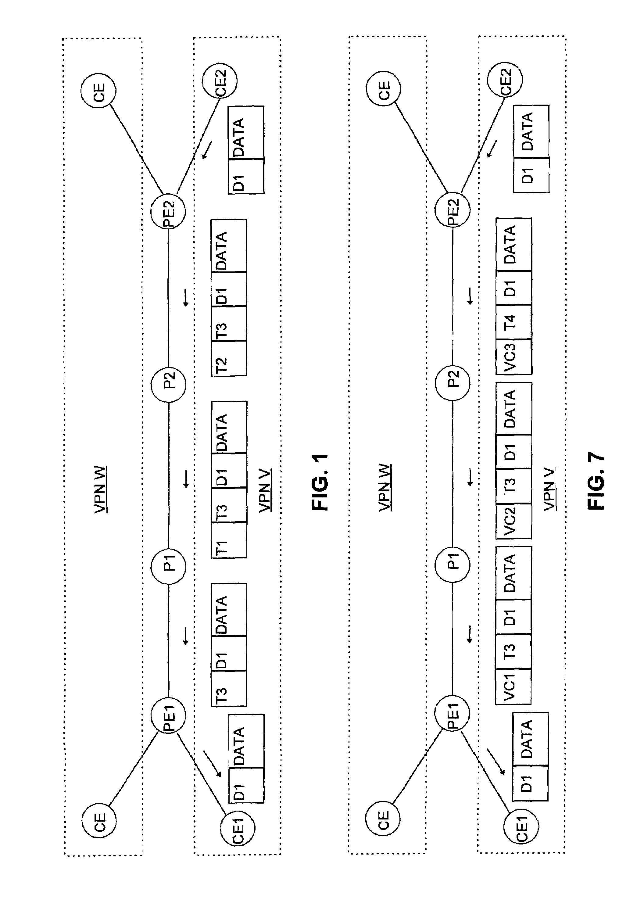
[0068]Before we describe an embodiment of the invention in detail, we will employ FIG. 1 to present a brief overview of its operation.

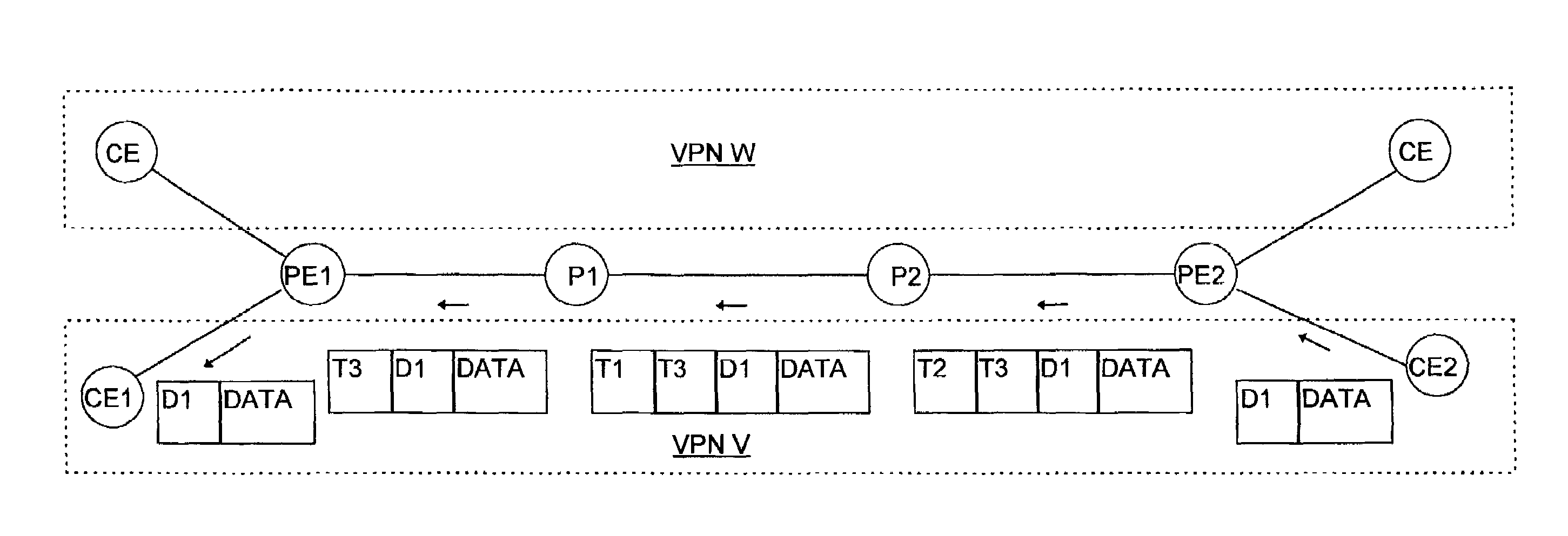
[0069]FIG. 1 depicts a very simplified topology for illustrating an SP's connections between two parts of a customer enterprise C's VPN. Two of the enterprise's edge routers CE1 and CE2 are located remotely from each other, and the customer enterprise has contracted with the SP to provide connections between the customer's routers such as CE1 and CE2 to form a VPN V. Among the SP's resources are edge routers PE1 and PE2 and further, transit routers P1 and P2 that together form a path between CE1 and CE2.

[0070]Consider a packet that a router CE2 receives from a location (not shown) in VPN V, and suppose that the contents D1 of the packet's destination-address field is the address of a system in VPN V at CE1's location. We assume that CE2 has interfaces over which it could potentially have forwarded the packet to routers, not shown in the drawin...


PUM


Abstract

A service provider's routers (PE1, P1, P2, PE2) provide connections between and share routing information with routers (CE1, CE2) of a customer virtual private network (VPN) as well as routers of other customers' VPNs, which may have overlapping address spaces. A service provider's edge router (PE1) informed by the customer's router (CE1) that it will forward packets to a given prefix notifies the other edge router (PE2) that PE1 can forward packets to that address prefix if the destination is in the VPN to which CE1 belongs. PE1 also tells PE2 to tag any thus-destined packets with a particular tag T3. PE2 stores this information in a forwarding information base that it separately keeps for that VPN so that when PE2 receives from a router CE2 in the same VPN a packet whose destination address has that prefix, it tags the packet as requested. But PE2 also tags it with a tag T2 that the router P2 to which PE2 first sends it has asked PE2 to apply to packets to be sent to PE1. P2 routes the packet in accordance with T2, sending it to P1 after replacing T2 with a tag T1 that P1 has similarly asked P2 to use. P1 removes T1 from the packet and forwards it in accordance with T1 to PE1, which in turn removes T3 from the packet and forwards it in accordance with T3 to CE1. In this manner, only the edge routers need to maintain separate routing information for separate VPNs.

Description

CROSS RELATED APPLICATIONS[0001]This application is a continuation of U.S. patent application Ser. No. 09 / 217,976 filed on Dec. 21, 1998, now U.S. Pat. No. 6,526,056; which is a continuation of U.S. patent application Ser. No. 08 / 997,343 filed on Dec. 23, 1997, now issued as U.S. Pat. No. 6,339,595 on Jan. 15, 2002.BACKGROUND OF THE INVENTION[0002]1. Field of the Invention[0003]The present invention is directed to communications networking. It is directed particularly to providing routing for private wide-area networks.[0004]2. Background Information[0005]An enterprise that has many sites can build a private wide-area network by placing routers at each site and using leased lines to interconnect them. A router that has a wide-area connection to another router may be called a “backbone router.” The “backbone network” is the set of backbone routers and their interconnections.[0006]If every backbone router is connected to every other backbone router, the backbone network is said to be ...

Claims


Application Information

Patent Timeline
IPC IPC(8): H04L12/28
CPCH04L12/465H04L45/04H04L45/50
Inventor REKHTER, YAKOVROSEN, ERIC C.
Owner CISCO TECH INC
Why Eureka
Try Eureka