FSK signal demodulation circuit

a demodulation circuit and signal technology, applied in the field of demodulation circuits for demodulating fsk signals, can solve the problems of large size and complicated circuit structure, and achieve the effect of improving demodulation performance, simple structure, and reducing size and weight of systems incorporating demodulation circuits

Inactive Publication Date: 2008-05-06
SEMICON COMPONENTS IND LLC
View PDF8 Cites 23 Cited by
  • Summary
  • Abstract
  • Description
  • Claims
  • Application Information

AI Technical Summary

Benefits of technology

[0009]The present invention attains simplification of a demodulation circuit to thereby reduce the size and weight of a system incorporating the demodulated circuit by employing the means described below.
[0013]As described above, according to the present invention, an FSK demodulation circuit having a relatively simple structure can be realized. As a result, the size and weight of a system which incorporates the demodulation circuit can be advantageously reduced, and additionally, the demodulation performance can be further improved.

Problems solved by technology

Although these demodulation circuits can exhibit preferable demodulation performance, they have a problem of a complicated circuit structure that is large in size.

Method used


Image

  • FSK signal demodulation circuit
  • FSK signal demodulation circuit
  • FSK signal demodulation circuit

Examples


Embodiment Construction

[0020]In the following, a preferred embodiment of the present invention is described with reference to the attached drawings.

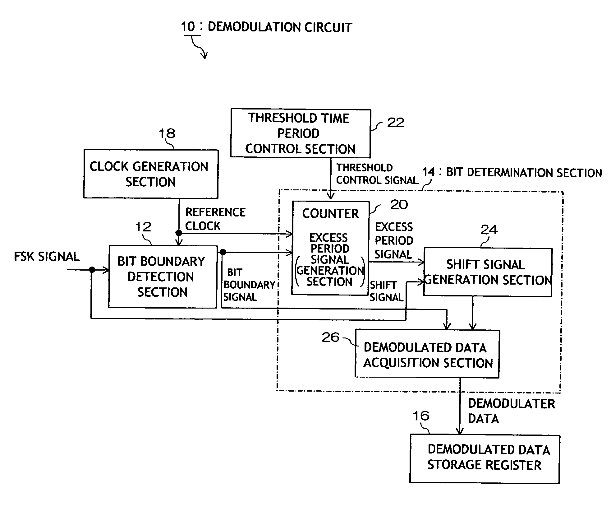
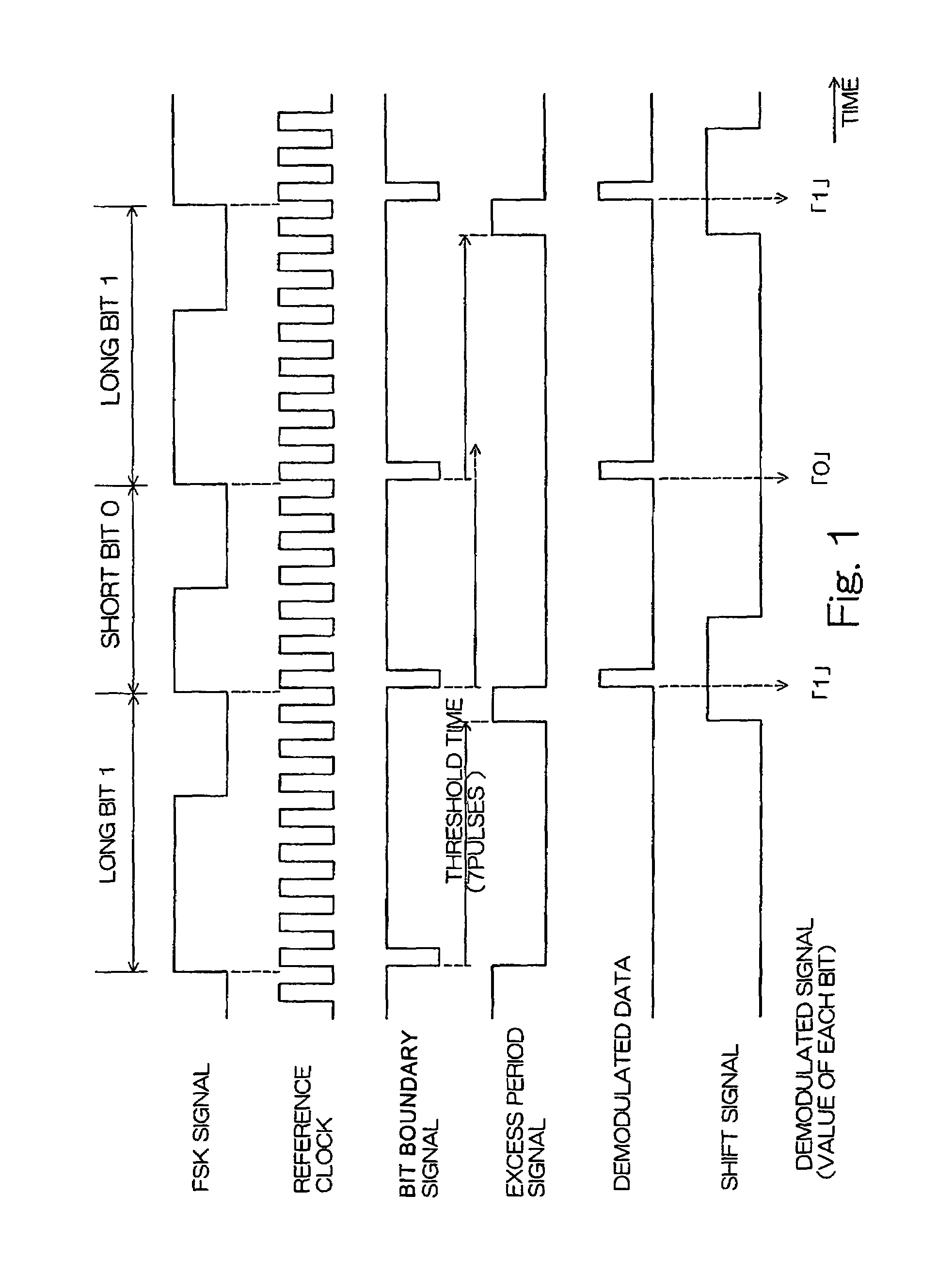
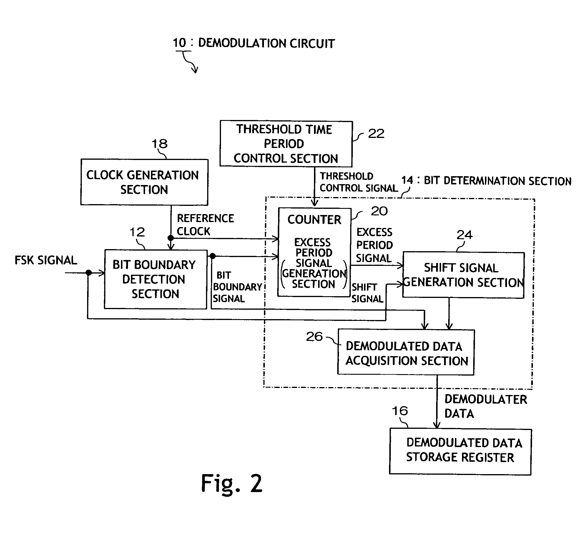
[0021]FIG. 1 is a timing chart for the signals employed in a demodulation circuit 10 in the embodiment. FIG. 2 is a block diagram showing an example of a demodulation circuit 10. FIG. 3 is a diagram showing an example of a circuit structure of a bit boundary detection section 12. FIG. 4 is a diagram showing an example of a circuit structure of a shift signal generation section 24, a demodulated data acquisition section 26, and a demodulated data storage register 16.

[0022]The demodulation circuit 10 shown in FIG. 2 comprises a bit boundary detection section 12, a bit determination section 14, a demodulated data storage register 16, and a clock generation section 18 for generating a reference clock pulse signal (hereinafter referred to as a reference clock).

[0023]The bit boundary detection section 12 detects a bit boundary of an FSK signal, which, in the case of...


PUM


Abstract

A demodulation circuit for demodulating an FSK signal comprising a long bit having a long bit period and a short bit having a short bit period comprises a bit boundary detection section for detecting a bit boundary timing of each bit, and a bit determination section for making determination for each bit such that a particular bit is determined to be a long bit when a threshold time period has passed during a period from a bit boundary timing at a leading end of the bit to a bit boundary timing at a trailing end of the bit, and a particular bit is determined to be a short bit when the threshold time period has not passed during a period from a bit boundary timing at a leading end of the bit to a bit boundary timing at a trailing end of the bit.

Description

CROSS-REFERENCE TO RELATED APPLICATION[0001]The entire disclosure of Japanese Patent Application No. 2003-309519 including specification, claims, drawings and abstract is incorporated herein by reference in its entirety.BACKGROUND OF THE INVENTION[0002]1. Field of the Invention[0003]The present invention relates to a demodulation circuit for demodulating an FSK signal which comprises a long bit pulse and a short bit pulse.[0004]2. Description of the Related Art[0005]An example of an FSK signal is described with reference to FIG. 5. As shown in FIG. 5, an FSK signal comprises a long bit, which has a long bit period, and a short bit, which has a short bit period. Note that a bit period is a combination of a period with a bit pulse and a period without a bit pulse. Each bit contains a single pulse having a certain length.[0006]In the example of FIG. 1, a long bit contains a pulse having a long length, while a short bit contains a pulse having a short length. Either one of the long or s...

Claims


Application Information

Patent Timeline
Patent Type & Authority Patents(United States)
IPC IPC(8): H03D3/00H04L27/22H04L27/14H04L25/49H04L27/156H04L27/26
CPCH04L25/4902H04L27/156H04L27/26
Inventor UMEWAKA, MASAHIRO
Owner SEMICON COMPONENTS IND LLC
Why Eureka
Try Eureka