Myocardial lead and lead system

a technology of myocardial lead and lead system, which is applied in the direction of heart stimulators, diagnostic recording/measuring, therapy, etc., can solve the problems of high morbidity, trauma and pain of patients, and the occurrence of undetectable bleeding in the thoracic cavity, so as to minimize the stress at the junction

Active Publication Date: 2008-05-06
PACESETTER INC
View PDF49 Cites 176 Cited by
  • Summary
  • Abstract
  • Description
  • Claims
  • Application Information

AI Technical Summary

Benefits of technology

[0010]In accordance with one specific, exemplary embodiment of the invention, there is provided an implantable myocardial stimulation lead comprising a lead body having a distal end and a proximal end, and an electrical connector carried by the proximal end of the lead body. An electrode header carried by the distal end of the lead body has an axis and includes a helical fixation element extending along the axis, the electrode header having a surface configured to receive a driver for rotating the electrode header to screw the helical fixation element into the tissue of the heart. In accordance with one particular form of the invention, the lead body and the electrode header are joined at a junction, the lead body extending proximally from the junction in a direction intermediate the direction of the header axis and the direction of a second axis transverse to the header axis. This geometry minimizes stress at the junction during implantation of the lead.
[0011]Pursuant to another specific, exemplary embodiment of the present invention, there is provided an implantable myocardial stimulation lead comprising a lead body having a distal end and a proximal end. The proximal end carries an electrical connector and the distal end carries an electrode header. The electrode header has an axis and includes a helical fixation element extending along the axis. The electrode header further has a surface configured to receive a driver for rotating the electrode header to screw the helical fixation element into the tissue of the heart. The distal end of the lead body has a flexible section extending from said electrode header, the flexible section providing strain relief. Preferably, the flexible section comprises a plurality of longitudinally spaced apart projections, adjacent projections interfering with one another upon bending of the distal end of the lead body through a predetermined radius of curvature to provide the mentioned strain relief.
[0015]Pursuant to another specific, exemplary embodiment of the invention, there is provided an introducer for facilitating the thoracoscopic delivery and implantation of an electrode header on the distal end of the lead body of a myocardial stimulation lead, the electrode header including a helical fixation element. The introducer comprises an elongated, tubular introducer body having a deflectable or steerable distal end section. A lumen extending the length of the introducer body is adapted to receive within the steerable distal end section of the introducer body a driver configured to mate with and drivingly implant the electrode header. By placing the lead body inside the tubular structure of the introducer body, wrapping of the lead body about the exterior of the introducer during lead implantation is avoided.

Problems solved by technology

Conventional implant approaches using current epi-myocardial leads have disadvantages including the relatively large incisions needed to gain access into the thoracic cavity and to the heart's LV; the difficulty of quickly and easily attaching the lead; the higher rate of morbidity, trauma and pain to the patient; the occurrence of undetectable bleeding in the thoracic cavity due to the larger incisions; the tendency to require longer recovery time in the hospital; and cosmetic disagreeability to the patients.
Examples of this kind of tool and lead body / header interconnection are disclosed in U.S. Pat. No. 4,972,847 issued Nov. 27, 1990, and titled “Pacing Lead and Introducer Therefor.” While lead bodies that extend radially outward from the electrode header at the junction thereof tend to conform more closely to the outer surface of the heart after implantation, the lead body is often subjected to high stresses during implantation because of the sharp bend imposed upon the lead body when the electrode header is temporarily held inside the introducer.
Introducers of this kind also tend to be relatively complex, comprising multiple parts that must be unlocked to release the lead and its electrode header from the introducer following implantation.
Such orientations can result in high stresses and fatigue damage at or near the lead body / electrode header interface.

Method used


Image

  • Myocardial lead and lead system
  • Myocardial lead and lead system
  • Myocardial lead and lead system

Examples


Embodiment Construction

[0064]The following description is of a best mode presently contemplated for practicing the invention. This description is not to be taken in a limiting sense but is made merely for the purpose of describing the general principles of the invention whose scope is defined by the appended claims. Although the invention will be described in the context of implantable cardiac stimulation and sensing leads, it will be evident to those skilled in the art that the invention described herein has broader utility, being applicable to a wide variety of implantable medical leads for stimulating selected body tissue and sensing the electrical activity of such tissue.

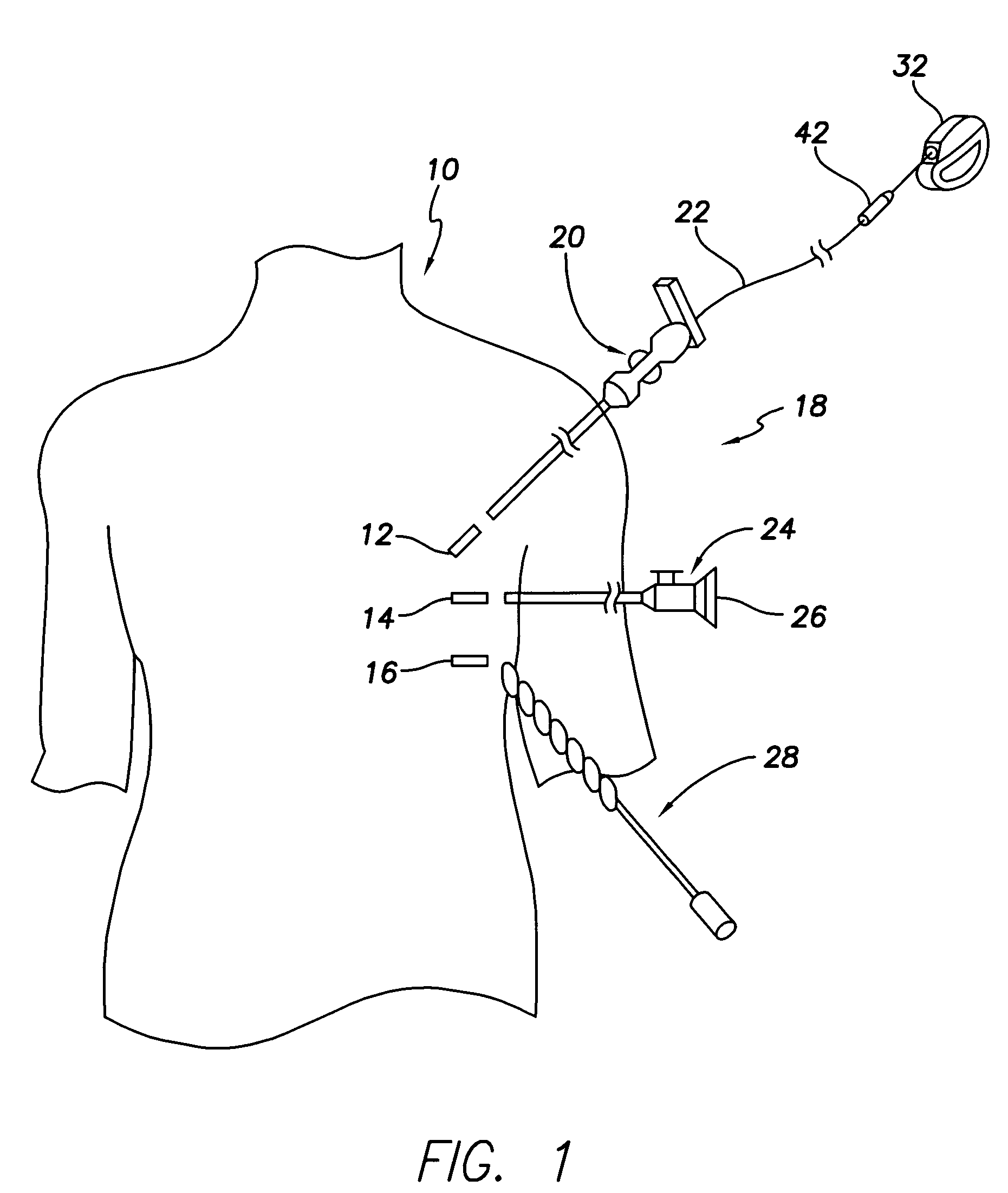
[0065]FIG. 1 illustrates schematically a patient's upper chest region 10 having formed therein three small or keyhole intercostal incisions 12, 14 and 16 for receiving various instruments of a myocardial implantation system 18 in accordance with the present invention. Although FIG. 1 illustrates three incisions, it will be evident tha...


PUM


Abstract

An implantable myocardial stimulation lead comprises a lead body having a distal end and a proximal end, and an electrical connector carried by the proximal end of the lead body. An electrode header carried by the distal end of the lead body has an axis and includes a helical fixation element extending along the axis, the electrode header having a surface configured to receive a driver for rotating the electrode header to screw the helical fixation element into the tissue of the heart. The lead body carries along its length a strain relief member resisting excessive bending of the lead body.

Description

CROSS REFERENCE TO RELATED APPLICATIONS[0001]This application claims the benefit of U.S. Provisional Application No. 60 / 543,897, filed Feb. 11, 2004, titled “Myocardial Lead System”; and is related to U.S. patent applications:1) Ser. No. 11 / 056,751, titled “Myocardial Lead and Lead System”; and2) Ser. No. 11 / 056,775, titled “Myocardial Lead and Lead System”; both of which also claim the benefit of U.S. Provisional Application No. 60 / 543,897, filed Feb. 11, 2004; all applications filed concurrently herewith.FIELD OF THE INVENTION[0002]The present invention relates generally to myocardial lead systems and particularly to improved myocardial leads and apparatus for delivering and implanting such leads.BACKGROUND OF THE INVENTION[0003]When an implantable cardiac stimulation and / or sensing lead is placed on the outer surface of the heart in a process known as epi-myocardial lead implantation, the heart is made accessible by entering through the chest wall. The two most commonly used proc...

Claims


Application Information

Patent Timeline
Patent Type & Authority Patents(United States)
IPC IPC(8): A61N1/362A61N1/05
CPCA61N1/059
Inventor MORGAN, KEVIN L.HELLAND, JOHN R.WILLIAMS, SHELDONCHITRE, YOUGANDHMCGARVEY, ANDREW W.FLECK, CHRISTOPHERPATEL, JNYANSALYS, SCOTTSCHIMKE, KERWYN
Owner PACESETTER INC
Why Eureka
Try Eureka