Method of controlling a gas combustor of a gas turbine

a gas turbine and combustor technology, applied in combustion control, turbine/propulsion engine ignition, burner ignition devices, etc., can solve the problems of a large amount of time and money, and the system control of the valve assembly is relatively complex, so as to maintain the flame stability of the gas combustor. stable, easy-to-use

Inactive Publication Date: 2008-05-13
ANSALDO ENERGIA SPA
View PDF11 Cites 7 Cited by
  • Summary
  • Abstract
  • Description
  • Claims
  • Application Information

AI Technical Summary

Benefits of technology

[0006]It is an object of the present invention to provide a method of controlling a gas turbine gas combustor, designed to provide a straightforward, low-cost solution to the aforementioned drawbacks, and which, preferably, provides for maintaining the gas combustor flame stable.

Problems solved by technology

In the known gas combustor described above, forming and / or connecting the conduits upstream from the central secondary burner nozzle involve / s a good deal of time and money, and relatively complex systems are required to control the valve assemblies.

Method used


Image

  • Method of controlling a gas combustor of a gas turbine
  • Method of controlling a gas combustor of a gas turbine
  • Method of controlling a gas combustor of a gas turbine

Examples


Embodiment Construction

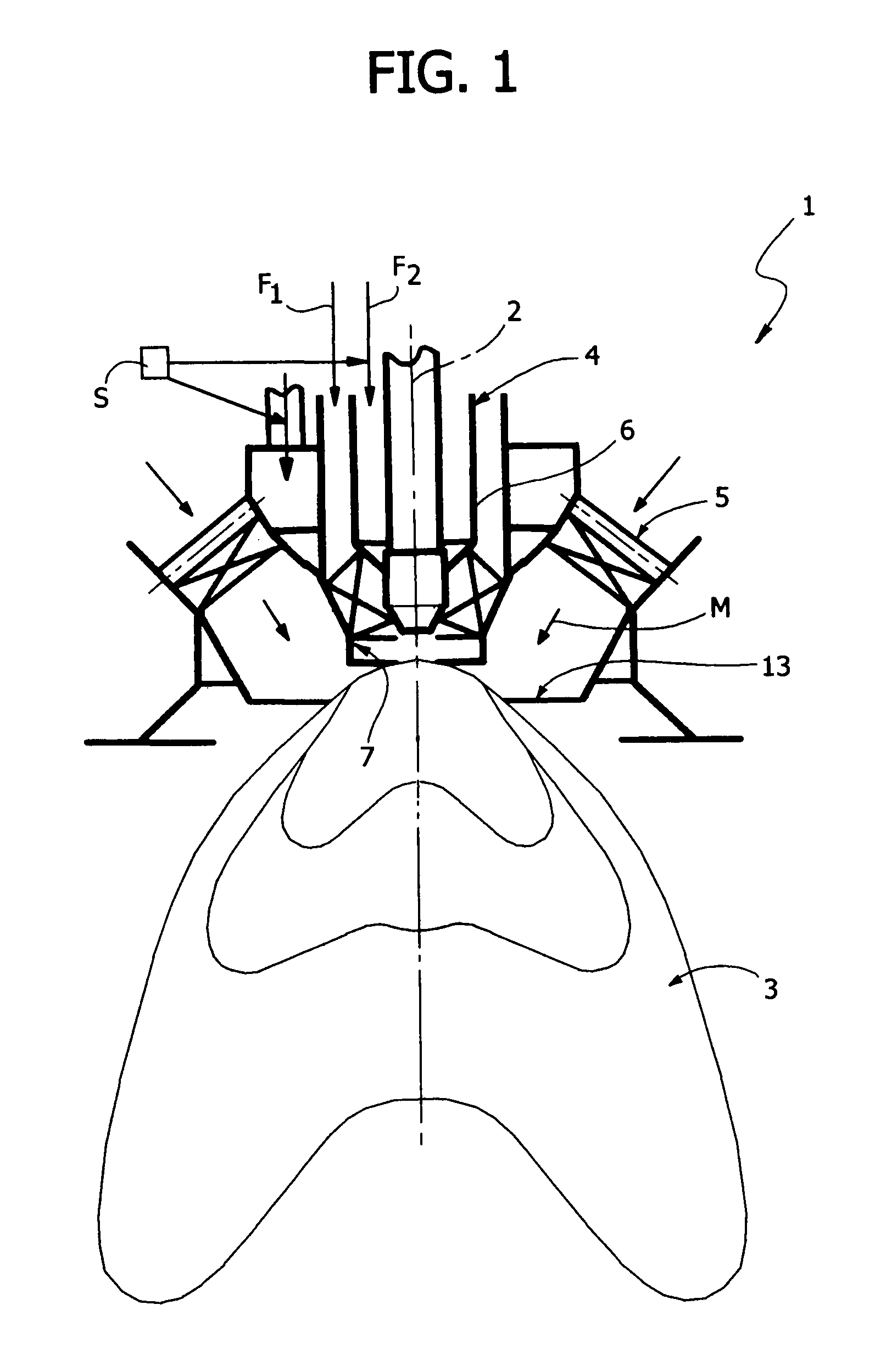
[0030]Number 1 in FIG. 1 indicates as a whole a gas combustor (shown partly and schematically) of a gas turbine.

[0031]Gas combustor 1 has an axis 2, and comprises a combustion chamber 3; a central diffusion burner 4; and a peripheral premix burner 5 surrounding burner 4.

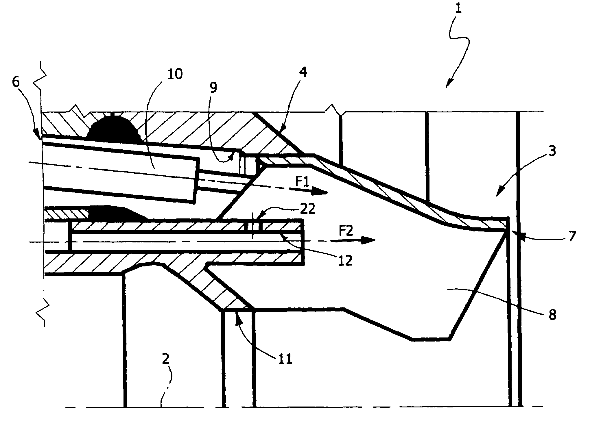
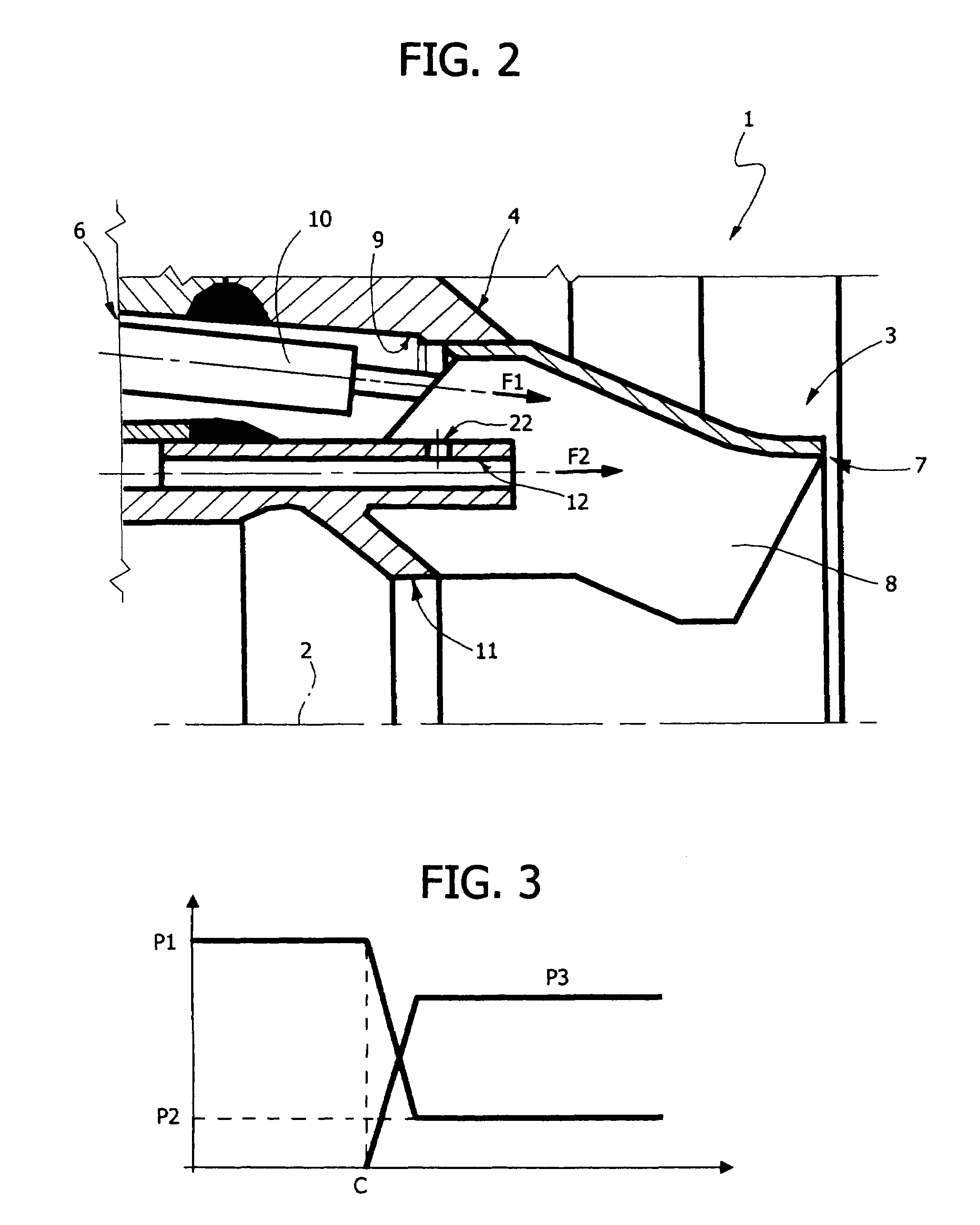
[0032]With reference to FIG. 2, burner 4 comprises an end nozzle 6 extending along axis 2 and having an axial outlet 7, which comes out inside chamber 3 and is fitted with vanes 8. Nozzle 6 defines a first channel 9 radially outwards with respect to axis 2 and housing a known ignition device 10; a second channel 11 extending along axis 2; and a third channel 12 interposed radially between and separate from channels 9 and 11.

[0033]As shown in FIG. 1, burner 5 has an outlet 13, which comes out inside chamber 3, surrounds outlet 7, and is also fitted with vanes to impart sufficient turbulence to a gas and air mixture M produced inside burner 5 from an incoming air stream and an incoming fuel gas stream, with an air quan...


PUM


Abstract

A gas combustor has a peripheral premix burner, and a central diffusion burner whose nozzle defines an eccentric first channel housing an ignition device, an axial second channel, and a third channel interposed radially between the first and second channel; the gas combustor is controlled, at a first start-up step, to keep the peripheral burner off and to feed a fuel gas stream along the third channel; at a second step, after a given load is exceeded, the peripheral burner is activated, and the gas stream in the central burner continues to be fed along the same channel as at the first step, and is regulated to reduce its flow to a value greater than zero.

Description

[0001]The present invention relates to a method of controlling a gas turbine gas combustor of the type comprising a combustion chamber, a peripheral main burner, and a central secondary burner. The peripheral main burner is a so-called “premix” type, i.e. receives a stream of fuel gas and a stream of air, which are mixed with a strong surplus of air with respect to the stoichiometric ratio) before being fed into the combustion chamber; while the central burner is a so-called “diffusion” type, i.e. feeds the fuel gas and air streams separately (with a practically stoichiometric ratio) into the combustion chamber, where mixing and combustion occur.BACKGROUND OF THE INVENTION[0002]As is known, a premix burner flame is characterized by lower temperature (1500° C. as compared with 2000° C. typical of a diffusion flame) and therefore lower nitric oxide emissions.[0003]In known solutions, the central secondary burner comprises a nozzle extending along the axis of the gas combustor, and whi...

Claims


Application Information

Patent Timeline
Patent Type & Authority Patents(United States)
IPC IPC(8): F02C7/26F02C9/26F23R3/28F23N1/02F23R3/34
CPCF02C9/26F23N1/02F23R3/286F23R3/343F23D2207/00F23D2900/00008F23N2037/10F23N2237/10
Inventor ROCCA, FRANCO
Owner ANSALDO ENERGIA SPA
Why Eureka
Try Eureka