Electromotive power assisted bicycle

a technology of electric power and bicycle, applied in the direction of bicycles, gearing details, transportation and packaging, etc., can solve the problems of loss of versatility, increase in cost, and components cannot be adapted to the frame of a regular bicycle, and achieve the effect of compact and simplified system, high processing function

Inactive Publication Date: 2008-05-13
SUNSTAR GIKEN KK +1
View PDF20 Cites 53 Cited by
  • Summary
  • Abstract
  • Description
  • Claims
  • Application Information

AI Technical Summary

Benefits of technology

[0015]Thus, the present invention does not employ a system as the crank coaxial output type of the force combining mechanism or the chain direct drive system according to the prior art, where an auxiliary power is transmitted directly to the portion whose position is defined geometrically, but a system in which the torque to be output from the power sprocket is transmitted to the secondary sprocket rotating coaxially with the primary sprocket via a separate auxiliary chain. This may allow the power sprocket to be installed in any desired location as long as the power sprocket does not interfere with the primary sprocket or other portions of the body frame, thus extending the degree of freedom for the installation of the electromotive power output unit box. For example, the power sprocket can be placed in any desired location along a circumferential direction of the secondary sprocket (and thus the primary sprocket). Further, if the length of the auxiliary chain is changed, the distance from the secondary sprocket (and thus the primary sprocket) to the power sprocket can be modified as desired.
[0032]Since the single chip control circuit of 16 bits at minimum has a high level of processing function, those functions inherent to a dedicated IC according to the prior art can be added to said single chip without applying a heavy load thereto, thus achieving a compact and simplified system for the electromotive power assisted bicycle. In addition, it allows for not only flexibility in implementing functional modifications in the future but also the ability to select any suitable software for bicycles of many different frames and to add any additional functions. Further, in the pulse width modulated control to the electric motor, since the control is always monitored by the software, the electric motor can be suspended immediately under any circumstances.

Problems solved by technology

However, in the above described prior art, since the electromotive power assisted bicycle is built by providing a specialized body for the electromotive power assisted bicycle and then mounting to said body respective components exclusively tailored therefor, the components can not be adapted to a frame for a regular bicycle, thereby losing versatility.
Therefore, those systems according to the prior arts have common problems that they may lead to an increase in cost as well as to a complicated mechanism, resultantly increasing the volume and weight of the electromotive power assisted bicycle.
In the above-mentioned force combining mechanism according to the prior art, the mechanism of crank coaxial output type needs to employ a structure different from a typical frame around the crank shaft, which may lead to a complex and enlarged profile of the structure around the crank shaft.
On the other hand, the prior art force combining mechanism relying on the direct chain drive system shown in FIG. 35 entails a problem that the force combining mechanism is installed exclusively in a location where the chain for transmitting the pedal effort runs therethrough, which is, in actual practice, in a position near the chain (an upper or a lower side thereof) located between the sprocket and a rear wheel.
Consequently, the force combining mechanism cannot be installed in a front side of the sprocket.
Further, in the mounting system of the battery according to the prior art as described above, since the battery is often placed longitudinally owing to the U-shaped attachment to be used, and in a case that the battery is moved in the vertical direction, a long distance must be provided between the attachment and a saddle, meaning a large space is necessary for attaching and detaching, thus a restriction is imposed on the body frame available for mounting the attachment.
Besides, in this mounting system, since the fastener has to be loosened or tightened in response to the detaching or attaching operation of the battery, the attaching and detaching operation takes time, and further disadvantageously, the system entails a problem that a third party may possibly loosen the fastener and steal the battery easily.
To satisfy these requirements, although in some practices according to the prior art a dedicated body frame has been made, or a special processing has been applied thereto, such attempts have not yet successfully utilized a regular frame manufacturing process.
Further, if the electromotive power output unit box is to be mounted without applying any modification to the frame, the electromotive power output unit itself, and attachments used to mount the unit to the frame are apt to be complicated, and furthermore, in such a case the difficulty in positioning is not avoidable.
Thus, in such an arrangement having distant screwed positions, if a gear such as a helical gear, for example, that produces a component force in an axial direction of the shaft is used, said component force in the axial direction may produce a deflection in the gear box (especially in the cover) thereby inducing a vibration thereof.
Further, since the gear box is deformed and thereby a pitch error may be produced between gears and also a perpendicularity of the gear mounting portion may be distorted, it is more likely to make a sound.

Method used


Image

  • Electromotive power assisted bicycle
  • Electromotive power assisted bicycle
  • Electromotive power assisted bicycle

Examples


third embodiment

[Third Embodiment of the Unit Mounting Bracket]

[0128]FIG. 19 shows a unit mounting bracket 300 according to a third embodiment, which is adaptable to bicycles with such frames, other than the diamond-shaped frame, as foldable bicycles or a light roadster bicycles, for example. The unit mounting bracket 300 comprises mainly a bottom plate 302, a pair of side plates 304R, 304L extending substantially in a vertical direction from the bottom plate 302, and an end plate 314 bent substantially at a right angle in an end portion of the bottom plate. The pair of side plates 304R, 304L comprises a pair of partial circular segments each having an outer circumference formed into a partial circle, and a pair of side extension segments 306R, 306L, extending from said bottom plate 302 substantially in the vertical direction along the length of the bottom plate as the extension segment of said partial circular segment, wherein said circular segments are provided with side holes 307R, 307L through ...

fourth embodiment

[Fourth Embodiment of the Unit Mounting Bracket]

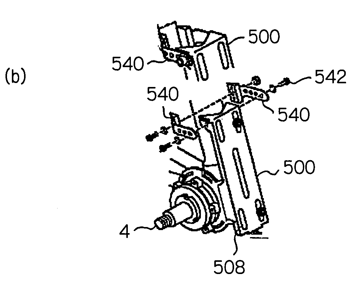
[0145]Fourth embodiment of the unit mounting bracket will now be described with reference to FIG. 27 and FIG. 29. As shown in FIG. 28, a unit mounting bracket is generally shown by reference numeral 500, and comprises mainly a bottom plate 502, a pair of side plates 504R, 504L extending substantially in a vertical direction from said bottom plate 502, a frame engaging portion 512 formed in one end of said bottom plate and an end plate 514 bent substantially at a right angle in the other end of said bottom plate.

[0146]A V-shaped concave surface to be engaged with the frame is formed in the frame engaging portion 512, while in the end plate 514 is formed a sliding-motion hole 516 which is to be engaged with a bolt (524 of FIG. 1) for allowing the electromotive power output unit box 13 to move slidably.

[0147]The pair of side plates 504R, 504L comprises a pair of partial circular segments, each having a periphery formed into a part of circ...

first embodiment

[First Embodiment of the Battery Bracket]

[0195]A detailed configuration of the battery bracket 165 according to a first embodiment will now be described with reference to FIGS. 21 through 24.

[0196]FIG. 21 shows a lower plan view, a front elevation view and a side elevation view of the bracket member 170. The bracket member 170 comprises a box section 171 configured to house a part of the battery 162 and an extension plate section 175 extending from a top plate 173U of the box section.

[0197]The box section 171 is defined by the top plate 173U, a bottom plate 173B, a pair of left and right side plates 172R, 172L, a curved section 178 formed into a curved contour mating to a frame of the seat post 3a so as to clamp it, mounting faces 174R, 174L located adjacent to the curved section 178 in the left and the right sides thereof to be used as mounting faces which are to be engaged with the bracket retainer 183 when the battery bracket 165 is mounted to the body frame, and a connecting sur...


PUM


Abstract

An electromotive power assisted bicycle includes a drive shaft rotated by a pedal effort a primary sprocket fixed to the drive shaft for transmitting the pedal effort to a drive wheel; a secondary sprocket fixed to the drive shaft coaxially with the primary sprocket; a pedal effort detection sensor; an electromotive power output unit box detachably attached to the body for outputting electromotive power in response to the detected pedal effort; a power sprocket coupled to a rotating output shaft of the electromotive power output unit box; an auxiliary chain stretched between the secondary sprocket and the power sprocket; a supporting section for rotatably supporting the drive shaft; and a unit mounting bracket on which the electromotive power output unit box is mounted, the unit mounting bracket being fixed to the supporting section with the drive shaft penetrating through the unit mounting bracket.

Description

FIELD OF THE INVENTION[0001]The present invention relates to an electromotive power assisted bicycle that can run under a pedal effort to be assisted by electromotive power; and more specifically to an electromotive power assisted bicycle wherein the attachment system of the electromotive power has a high degree of flexibility for installation thereof.BACKGROUND OF THE INVENTION[0002]Conventionally, an electromotive power assisted bicycle that can run under a pedal effort assisted by electromotive power has been made using a body frame tailored specifically for such a bicycle, and the frame has been further built upon by incorporating an electric motor, a reduction gear, a battery and other components such as a force combining mechanism for adding the electromotive power to the pedal effort. Those components have also been fabricated as dedicated parts adapted to the dedicated body frame.[0003]Among the above components, an example of a type of mechanism that has been suggested as t...

Claims


Application Information

Patent Timeline
Patent Type & Authority Patents(United States)
IPC IPC(8): B62K11/00B62M6/45B62M6/55B62M6/80F16H57/028F16H57/029F16H57/03F16H57/031
CPCB62M6/45B62M6/55
Inventor KOKATSU, KYOSUKEYOSHIIE, AKIHITONIGARA, FUMIHITO
Owner SUNSTAR GIKEN KK
Why Eureka
Try Eureka