
Rigid vehicle axle with integral trailing arms

a technology of trailing arms and axles, which is applied in the direction of axle units, vehicle springs, transportation and packaging, etc., can solve the problems of reducing the size affecting the weight etc., and achieves and the reduction of the unsprung mass

Active Publication Date: 2008-05-13
JOST WERKE
View PDF25 Cites 10 Cited by
  • Summary
  • Abstract
  • Description
  • Claims
  • Application Information

AI Technical Summary

Benefits of technology

[0009]No, or only short, centering overlaps of the sections in the areas of the weld seams substantially avoid material doublings in the weld zone. In this way, inter alia, the axle weight is reduced without a loss of strength. In order to reduce the axle weight further, thinner wall thicknesses for the axle tube are selected than the wall thicknesses of the trailing arms which are subject to high loads. Since, at the same time, the axle tube sections generally have a larger average diameter than the hollow-profile regions of the trailing arm sections, these different axle assemblies are adapted to the load profile in an optimum way in terms of strength and rigidity.
[0010]The weight reduction reduces the unsprung axle mass, thereby, among other things, reducing the susceptibility of the rigid axle to bumping. This improves road adhesion and hence driving safety. It also has a positive effect on the life of the tires.

Problems solved by technology

Such material doublings and stiffening measures have a detrimental effect on the size of the unsprung mass.

Method used


Image

  • Rigid vehicle axle with integral trailing arms
  • Rigid vehicle axle with integral trailing arms
  • Rigid vehicle axle with integral trailing arms

Examples


Embodiment Construction

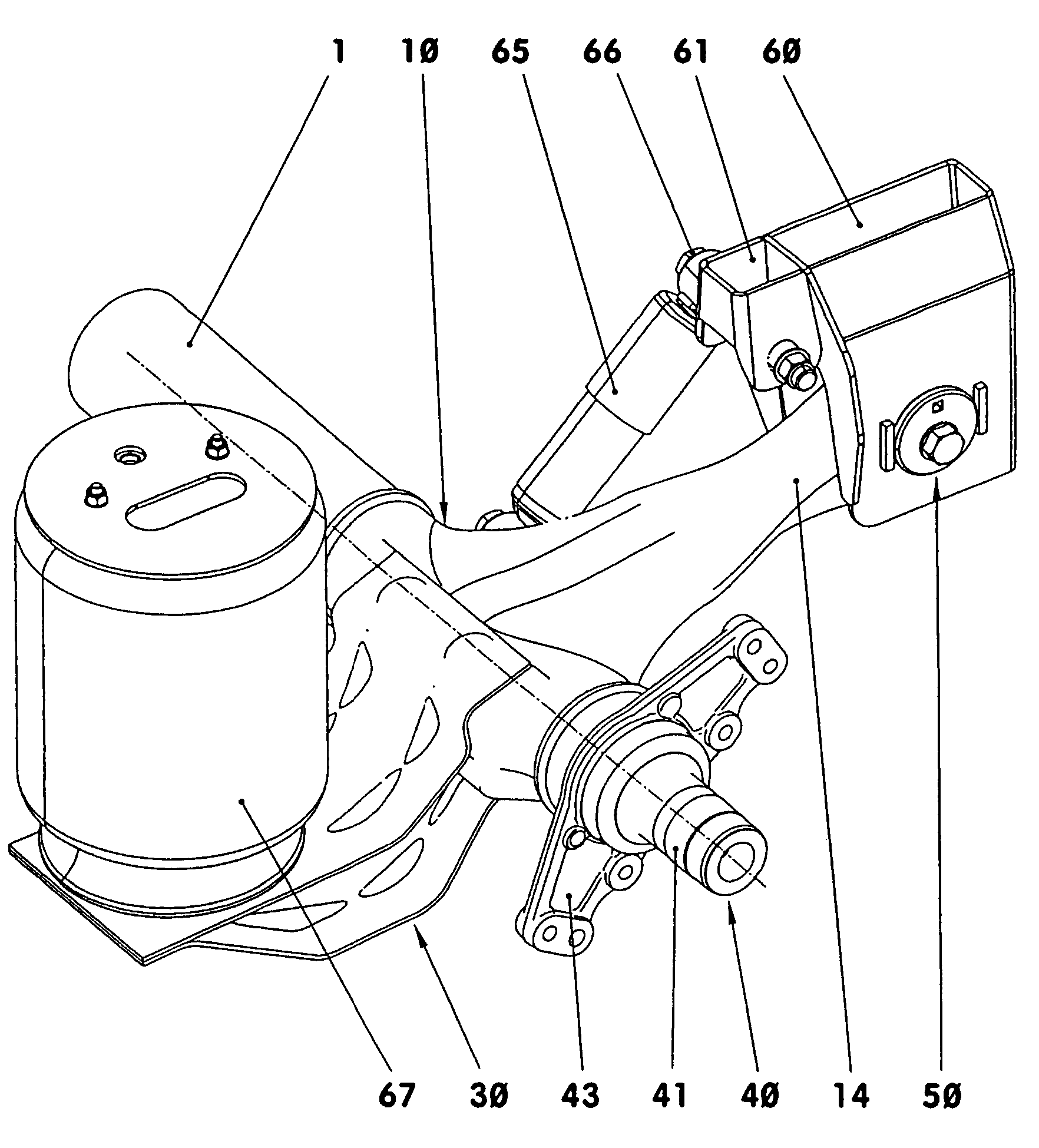
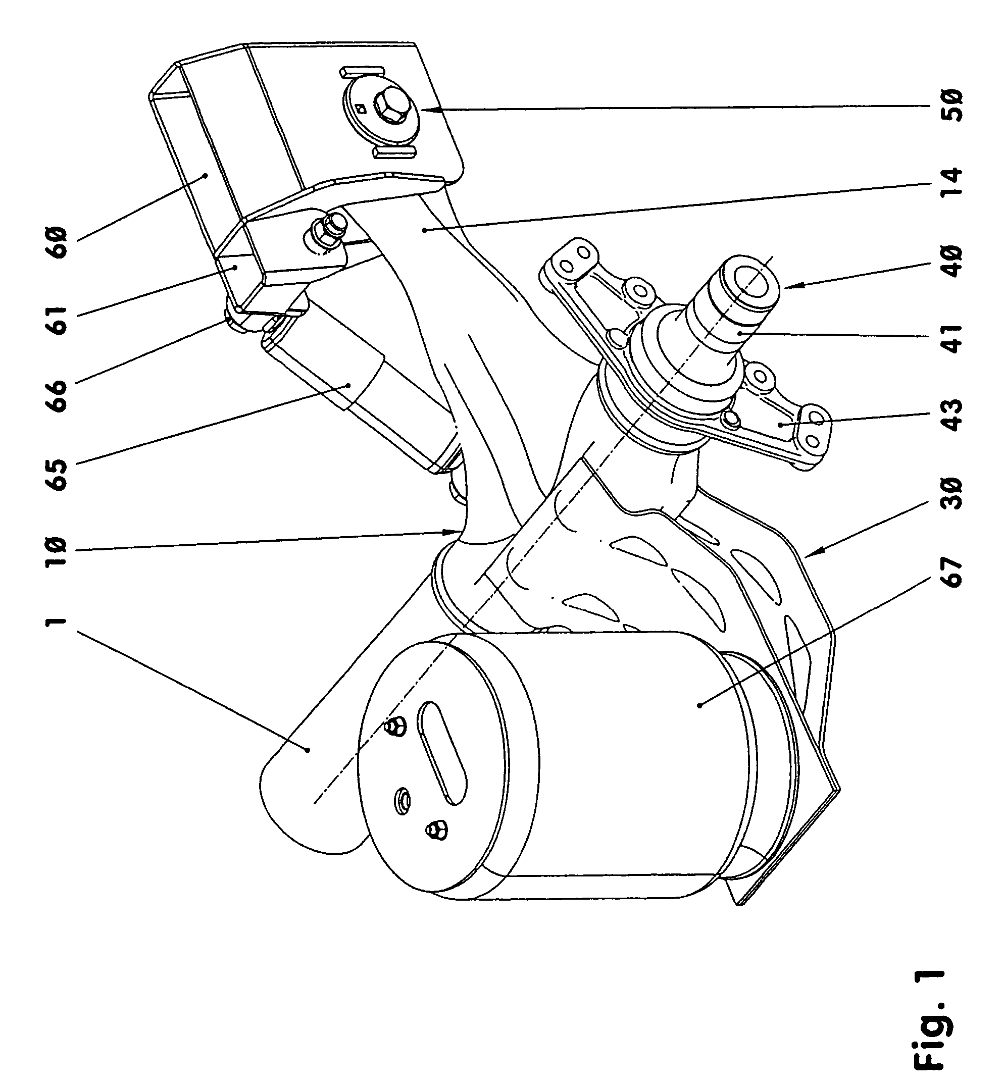
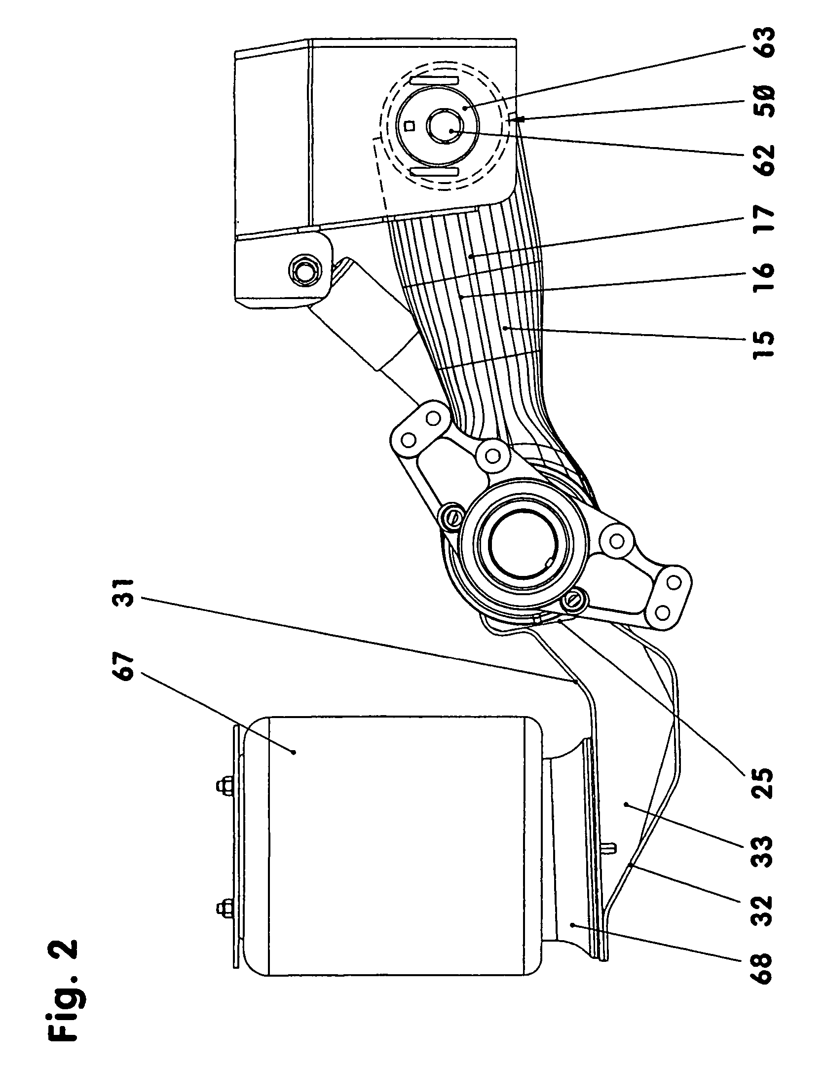
[0017]FIGS. 1 to 3 show, by way of example, a right-hand outer area of an axle of a towed commercial vehicle trailer or semitrailer without wheel and brake.

[0018]According to FIG. 1 the axle part shown comprises an axle tube section 1, a right-hand trailing arm section 10 and a wheel head section 40. At its front end—pointing in the direction of travel, for example—the trailing arm section 10 is fixed by means of an elastomer body in a bearing bracket 60 supported on the vehicle body side, so that it can swivel universally in an articulated bearing 50. It is braced in relation to the bearing bracket 60 by means of a shock absorber 65. The rear end of the trailing arm section 10 is braced on the vehicle body (not shown) by way of an air spring 67.

[0019]The axle tube section 1 comprises, for example, a smooth, cylindrical axle tube. The axle tube section 1, which is a hollow round body may also have a polygonal profile. It terminates directly at the trailing arm section 10 with a stra...


PUM


Abstract

In a rigid vehicle axle comprising an axle beam with axle journals forming wheel carriers arranged at the ends thereof, and at least two trailing arms rigidly fixed to the axle beam, each half of the rigid vehicle axle comprises an axle beam section, a trailing arm section and a wheel head section arranged adjacent one after another and the ends of the axle tube sections overlap with the adjoining ends of the trailing arm sections and their end faces are congruent with the respectively adjoining end faces of the wheel head sections, at least in some areas, and the adjoining sections are welded together.

Description

[0001]This is a Continuation-In-Part application of International Application PCT / EP2003 / 005684 filed May 30, 2003 and claiming the priority of German application 102 31 377.6 filed Jul. 11, 2002.BACKGROUND OF THE INVENTION[0002]The invention relates to a rigid vehicle axle comprising an axle beam with axle journals or wheel carriers arranged at the ends thereof, and at least two trailing arms rigidly fixed to the axle beam, each half of the vehicle rigid axle—as viewed from the center of the axle—comprising, arranged one after the other, an axle beam section, a trailing arm section and a wheel head section and the wheel head section comprising at least an axle journal or wheel carrier.[0003]DE 296 16 257 U1 representing the generic type of such an axle discloses a pneumatically suspended rigid vehicle axle, which comprises an axle tube and trailing arms welded thereto. Trailing arms with corresponding socket holes are pushed on to the axle tube, which is in the form of an axle jour...

Claims


Application Information

Patent Timeline
Patent Type & Authority Patents(United States)
IPC IPC(8): B60G9/00B60B35/16B60B35/00B60B35/04B60B35/08
CPCB60B35/04B60G9/003B60G2200/31B60G2202/152B60G2206/31B60G2206/8201
Inventor ABRAT, DUNJASCHUTTE, OLAF
Owner JOST WERKE
Learn More